Deck 5: Transistor Bias Circuits
ملء الشاشة (f)
سؤال
 Figure 1
Refer to Figure 1. The end points of the dc load line are at approximately
A)7 mA and 8 V
B)15 mA and 15 V
C)8 mA and 7 V
D)0 mA and 15 V
سؤال
سؤال
 Figure 4
Refer to Figure 4. Assume you were troubleshooting and found that VE is exactly the same as VEE. The trouble could be caused by
A)shorted RC
B)open RB
C)open RE
D)any of the above
سؤال
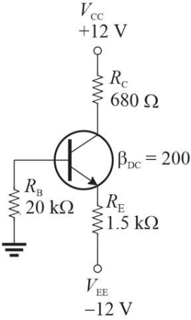 Figure 4
Refer to Figure 4. The emitter voltage, VE is approximately
A)-6.4 V
B)-3.8 V
C)-5.2 V
D)-1.4 V
سؤال
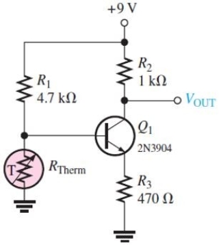 Figure 7
Refer to Figure 3. Note the transistor is a pnp type. The value of IC is approximately
A)1.0 mA
B)3.4 mA
C)2.5 mA
D)1.3 mA
سؤال
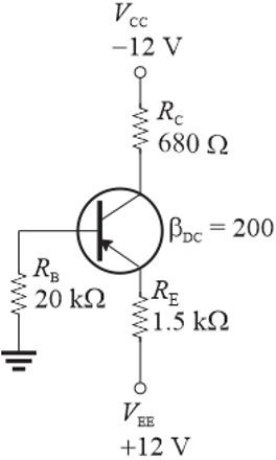 Figure 5 (This is similar to Figure 4 but uses a pnp transistor with the same fi.)
Refer to Figure 5. If RB is increased, VE will
A)decrease
B)increase
C)not change
سؤال
سؤال
سؤال
 Figure 1
Refer to Figure 1. The Q- point is approximately at
A)6.6 mA and 8.4 V
B)8.4 mA and 6.6 V
C)8.4 mA and 8.4 V
D)6.6 mA and 6.6 V
سؤال
Figure 5 (This is similar to Figure 4 but uses a pnp transistor with the same fi.)Refer to Figure 5. The expected emitter voltage is
A)the same as the collector voltage in the npn circuit
B)the same as the npn circuit
C)the same as the collector voltage in the npn circuit except for the sign
D)the same as the npn circuit except for the sign
سؤال
Figure 7Refer to Figure 7. Assume the thermistor has a resistance of 1.7 k▲. VOUT is approximately
A)5.9 V
B)4.7 V
C)7.5 V
D)5.4 V
سؤال
سؤال
سؤال
Figure 7Refer to Figure 7. The input resistance of RIN(BASE)
A)depends on the fi of the transistor
B)depends on the resistance of RE
C)both A and B
D)none of the above
سؤال
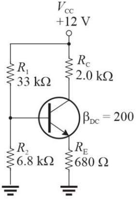 Figure 2
Refer to Figure 2. VCE is approximately
A)5.3 V
B)8.5 V
C)3.2 V
D)6.6 V
سؤال
 Figure 5 (This is similar to Figure 4 but uses a pnp transistor with the same fi.)
Refer to Figure 5. If RC is replaced with a 1.5 k▲ resistor, you would expect to see a large change in
A)IE
B)VE
C)VCE
D)all of the above
سؤال
سؤال
 Figure 2
Refer to Figure 2. The value of IC is approximately
A)2.6 mA
B)3.3 mA
C)1.3 mA
D)2.0 mA
سؤال
 Figure 5 (This is similar to Figure 4 but uses a pnp transistor with the same fi.)
Refer to Figure 5. If the transistor is replaced with a lower fi one, there will be
A)a small increase in IE
B)a large change in IE
C)a small decrease in IE
D)no change in IE
سؤال
 Figure 4
Refer to Figure 4. The type of bias shown is
A)emitter bias
B)collector feedback bias
C)emitter- feedback bias
D)dual supply base bias
سؤال
سؤال
سؤال
 Figure 4
Refer to Figure 4. If you wanted to develop the equation for IE,
A)assume VCE = VRC; apply Ohm's law to find IC first; then solve for IE
B)write KVL around the base- emitter circuit
C)Thevenize the base input circuit and apply Ohm's law
D)write KVL through the emitter and collector and both power supplies
سؤال
سؤال
سؤال
سؤال
سؤال
سؤال
سؤال
سؤال
 Figure 5 (This is similar to Figure 4 but uses a pnp transistor with the same fi.)
Refer to Figure 5. If RB is increased, VCE will
A)decrease
B)increase
C)not change

فتح الحزمة
قم بالتسجيل لفتح البطاقات في هذه المجموعة!
Unlock Deck
Unlock Deck
1/31
العب
ملء الشاشة (f)
Deck 5: Transistor Bias Circuits
1
Figure 1Refer to Figure 1. The end points of the dc load line are at approximately
A)7 mA and 8 V
B)15 mA and 15 V
C)8 mA and 7 V
D)0 mA and 15 V
B
2
At cutoff,
A)VCE = VCC
B)VB = 0.7 V
C)IC = IC(sat)
D)VCE = 1/2 VCC
A)VCE = VCC
B)VB = 0.7 V
C)IC = IC(sat)
D)VCE = 1/2 VCC
A
3
Figure 4Refer to Figure 4. Assume you were troubleshooting and found that VE is exactly the same as VEE. The trouble could be caused by
A)shorted RC
B)open RB
C)open RE
D)any of the above
B
4
Figure 4Refer to Figure 4. The emitter voltage, VE is approximately
A)-6.4 V
B)-3.8 V
C)-5.2 V
D)-1.4 V
فتح الحزمة
افتح القفل للوصول البطاقات البالغ عددها 31 في هذه المجموعة.
فتح الحزمة
k this deck
5
Figure 7Refer to Figure 3. Note the transistor is a pnp type. The value of IC is approximately
A)1.0 mA
B)3.4 mA
C)2.5 mA
D)1.3 mA
فتح الحزمة
افتح القفل للوصول البطاقات البالغ عددها 31 في هذه المجموعة.
فتح الحزمة
k this deck
6
Figure 5 (This is similar to Figure 4 but uses a pnp transistor with the same fi.)Refer to Figure 5. If RB is increased, VE will
A)decrease
B)increase
C)not change
فتح الحزمة
افتح القفل للوصول البطاقات البالغ عددها 31 في هذه المجموعة.
فتح الحزمة
k this deck
7
Refer to Figure 6. Assume VC = 0.07 V and VB = 0.7 V. The fault may be that
A)VCC has dropped to 8 V
B)RC is open
C)VCC is open
D)RE is open
A)VCC has dropped to 8 V
B)RC is open
C)VCC is open
D)RE is open
فتح الحزمة
افتح القفل للوصول البطاقات البالغ عددها 31 في هذه المجموعة.
فتح الحزمة
k this deck
8
Assume a pnp transistor is used in a voltage- divider biased circuit. If VB = -2.8 V, VE should be
A)+3.5 V
B)- 3.5 V
C)- 2.1 V
D)- 2.8 V
A)+3.5 V
B)- 3.5 V
C)- 2.1 V
D)- 2.8 V
فتح الحزمة
افتح القفل للوصول البطاقات البالغ عددها 31 في هذه المجموعة.
فتح الحزمة
k this deck
9
Figure 1Refer to Figure 1. The Q- point is approximately at
A)6.6 mA and 8.4 V
B)8.4 mA and 6.6 V
C)8.4 mA and 8.4 V
D)6.6 mA and 6.6 V
فتح الحزمة
افتح القفل للوصول البطاقات البالغ عددها 31 في هذه المجموعة.
فتح الحزمة
k this deck
10
Figure 5 (This is similar to Figure 4 but uses a pnp transistor with the same fi.)Refer to Figure 5. The expected emitter voltage is
A)the same as the collector voltage in the npn circuit
B)the same as the npn circuit
C)the same as the collector voltage in the npn circuit except for the sign
D)the same as the npn circuit except for the sign
فتح الحزمة
افتح القفل للوصول البطاقات البالغ عددها 31 في هذه المجموعة.
فتح الحزمة
k this deck
11
Figure 7Refer to Figure 7. Assume the thermistor has a resistance of 1.7 k▲. VOUT is approximately
A)5.9 V
B)4.7 V
C)7.5 V
D)5.4 V
فتح الحزمة
افتح القفل للوصول البطاقات البالغ عددها 31 في هذه المجموعة.
فتح الحزمة
k this deck
12
A stiff voltage divider is one in which
A)the Q- point will be centered
B)has very large bias resistors
C)loading effects can be ignored
D)two voltage sources are used
A)the Q- point will be centered
B)has very large bias resistors
C)loading effects can be ignored
D)two voltage sources are used
فتح الحزمة
افتح القفل للوصول البطاقات البالغ عددها 31 في هذه المجموعة.
فتح الحزمة
k this deck
13
Assume a load line is drawn for a transistor amplifier. If VCC is increased, the load line will
A)have a higher cutoff voltage
B)have a higher saturation current
C)both A and B
D)none of the above
A)have a higher cutoff voltage
B)have a higher saturation current
C)both A and B
D)none of the above
فتح الحزمة
افتح القفل للوصول البطاقات البالغ عددها 31 في هذه المجموعة.
فتح الحزمة
k this deck
14
Figure 7Refer to Figure 7. The input resistance of RIN(BASE)
A)depends on the fi of the transistor
B)depends on the resistance of RE
C)both A and B
D)none of the above
فتح الحزمة
افتح القفل للوصول البطاقات البالغ عددها 31 في هذه المجموعة.
فتح الحزمة
k this deck
15
Figure 2Refer to Figure 2. VCE is approximately
A)5.3 V
B)8.5 V
C)3.2 V
D)6.6 V
فتح الحزمة
افتح القفل للوصول البطاقات البالغ عددها 31 في هذه المجموعة.
فتح الحزمة
k this deck
16
Figure 5 (This is similar to Figure 4 but uses a pnp transistor with the same fi.)Refer to Figure 5. If RC is replaced with a 1.5 k▲ resistor, you would expect to see a large change in
A)IE
B)VE
C)VCE
D)all of the above
فتح الحزمة
افتح القفل للوصول البطاقات البالغ عددها 31 في هذه المجموعة.
فتح الحزمة
k this deck
17
Of the methods shown below, the one that has the most stability is
A)collector feedback bias
B)base bias
C)emitter bias
D)emitter feedback bias
A)collector feedback bias
B)base bias
C)emitter bias
D)emitter feedback bias
فتح الحزمة
افتح القفل للوصول البطاقات البالغ عددها 31 في هذه المجموعة.
فتح الحزمة
k this deck
18
Figure 2Refer to Figure 2. The value of IC is approximately
A)2.6 mA
B)3.3 mA
C)1.3 mA
D)2.0 mA
فتح الحزمة
افتح القفل للوصول البطاقات البالغ عددها 31 في هذه المجموعة.
فتح الحزمة
k this deck
19
Figure 5 (This is similar to Figure 4 but uses a pnp transistor with the same fi.)Refer to Figure 5. If the transistor is replaced with a lower fi one, there will be
A)a small increase in IE
B)a large change in IE
C)a small decrease in IE
D)no change in IE
فتح الحزمة
افتح القفل للوصول البطاقات البالغ عددها 31 في هذه المجموعة.
فتح الحزمة
k this deck
20
Figure 4Refer to Figure 4. The type of bias shown is
A)emitter bias
B)collector feedback bias
C)emitter- feedback bias
D)dual supply base bias
فتح الحزمة
افتح القفل للوصول البطاقات البالغ عددها 31 في هذه المجموعة.
فتح الحزمة
k this deck
21
IC and IE are nearly the same in a properly biased transistor.
فتح الحزمة
افتح القفل للوصول البطاقات البالغ عددها 31 في هذه المجموعة.
فتح الحزمة
k this deck
22
Voltage- divider bias requires two power supplies.
فتح الحزمة
افتح القفل للوصول البطاقات البالغ عددها 31 في هذه المجموعة.
فتح الحزمة
k this deck
23
Figure 4Refer to Figure 4. If you wanted to develop the equation for IE,
A)assume VCE = VRC; apply Ohm's law to find IC first; then solve for IE
B)write KVL around the base- emitter circuit
C)Thevenize the base input circuit and apply Ohm's law
D)write KVL through the emitter and collector and both power supplies
فتح الحزمة
افتح القفل للوصول البطاقات البالغ عددها 31 في هذه المجموعة.
فتح الحزمة
k this deck
24
RIN(BASE)will increase if IE decreases.
فتح الحزمة
افتح القفل للوصول البطاقات البالغ عددها 31 في هذه المجموعة.
فتح الحزمة
k this deck
25
The dc load line is a straight line drawn from IC(sat)to VCC.
فتح الحزمة
افتح القفل للوصول البطاقات البالغ عددها 31 في هذه المجموعة.
فتح الحزمة
k this deck
26
Base bias is more stable than voltage- divider bias.
فتح الحزمة
افتح القفل للوصول البطاقات البالغ عددها 31 في هذه المجموعة.
فتح الحزمة
k this deck
27
Collector feedback bias uses a form of negative feedback.
فتح الحزمة
افتح القفل للوصول البطاقات البالغ عددها 31 في هذه المجموعة.
فتح الحزمة
k this deck
28
VBE of properly biased pnp transistor is a positive value.
فتح الحزمة
افتح القفل للوصول البطاقات البالغ عددها 31 في هذه المجموعة.
فتح الحزمة
k this deck
29
Assume the output of an amplifier has both peaks clipped. This can be caused by
A)too little gain
B)Q- point is not centered
C)power supply voltage is too high
D)all of the above
A)too little gain
B)Q- point is not centered
C)power supply voltage is too high
D)all of the above
فتح الحزمة
افتح القفل للوصول البطاقات البالغ عددها 31 في هذه المجموعة.
فتح الحزمة
k this deck
30
The Q- point can be anywhere along the dc load line.
فتح الحزمة
افتح القفل للوصول البطاقات البالغ عددها 31 في هذه المجموعة.
فتح الحزمة
k this deck
31
Figure 5 (This is similar to Figure 4 but uses a pnp transistor with the same fi.)Refer to Figure 5. If RB is increased, VCE will
A)decrease
B)increase
C)not change
فتح الحزمة
افتح القفل للوصول البطاقات البالغ عددها 31 في هذه المجموعة.
فتح الحزمة
k this deck
فتح الحزمة
افتح القفل للوصول البطاقات البالغ عددها 31 في هذه المجموعة.


