Deck 2: Diodes and Applications
ملء الشاشة (f)
سؤال
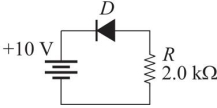 Figure 4
Refer to Figure 4. Assume the diode is a practical diode. If the diode is reversed, the current in the diode will be
A)0 mA
B)4.7 mA
C)5.7 mA
D)0.2 mA
سؤال
سؤال
سؤال
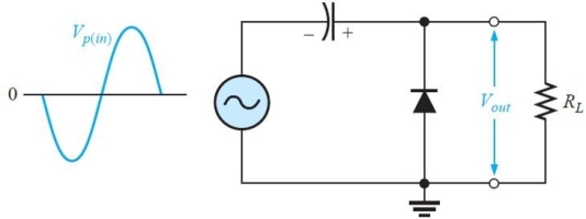 Figure 8
The maximum output voltage for the circuit in Figure 8 is approximately (Assume an ideal diode.)
A)Vp(in)
B)2Vp(in)
C)-Vp(in)
D)0 V
سؤال
 Figure 5
Refer to the circuit in Figure 5. The rms primary current is approximately
A)5.0 mA
B)500 mA
C)50 mA
D)0.5 mA
سؤال
سؤال
سؤال
 Figure 2
Refer to Figure 2. The circuit that will produce a positive output is
A)(a)
B)(b)
C)(c)
D)(d)
سؤال
سؤال
سؤال
سؤال
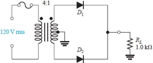 Figure 1
The circuit in Figure 1 is a
A)clamping circuit
B)bridge rectifier
C)center- tapped full- wave rectifier
D)half- wave rectifier
سؤال
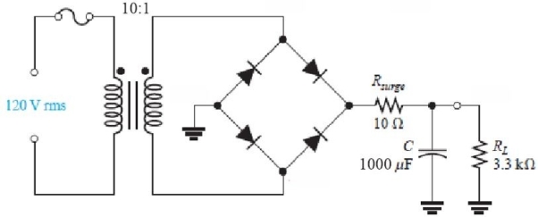 Figure 5
Refer to the circuit in Figure 5. The purpose of Rsurge is to
A)prevent load current from exceeding safe limits
B)prevent overheating the transformer
C)prevent an inrush of current that could damage diodes
D)all of the above
سؤال
سؤال
سؤال
سؤال
 Figure 8
The circuit in Figure 8 is a
A)negative clipping circuit
B)negative clamping circuit
C)positive clipping circuit
D)positive clamping circuit
سؤال
سؤال
C:\User  Figure 7
For questions 34, 35, and 36, assume ideal diodes
Which circuit in Figure 6 will produce the waveform in Figure 7(c)?
A)(a)
B)(b)
C)(c)
D)(d)
Figure 7For questions 34, 35, and 36, assume ideal diodes
Which circuit in Figure 6 will produce the waveform in Figure 7(c)?
A)(a)
B)(b)
C)(c)
D)(d)
سؤال
سؤال
سؤال
 Figure 1
For the circuit in Figure 1, assume ideal diodes. The peak inverse voltage is approximately
A)42 V
B)21 V
C)36 V
D)0 V
سؤال
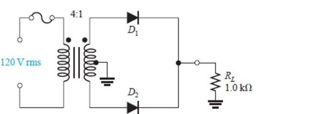 Figure 1
For the circuit in Figure 1, assume ideal diodes. The average voltage you should observe across RL is
A)13.5 V
B)19.2 V
C)9.6 V
D)27.0 V
سؤال
سؤال
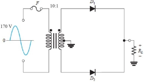 Figure 3
For the circuit in Figure 3, assume practical diodes. The peak output voltage across the load is
A)16.3 V
B)17.7 V
C)7.8 V
D)9.2 V
سؤال
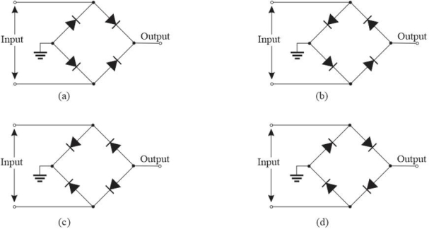 Figure 2
Refer to Figure 2. The circuit that will produce a negative output is
A)(a)
B)(b)
C)(c)
D)(d)
سؤال
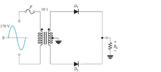 Figure 3
For the circuit in Figure 3, assume a diode opens. As a result, the peak output voltage will be
A)larger
B)zero
C)approximately the same
D)halved
سؤال
سؤال
سؤال
سؤال
سؤال
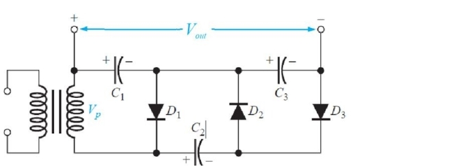 Figure 9
The circuit in Figure 9 is a
A)clipping circuit
B)voltage doubler
C)voltage tripler
D)limiter circuit
سؤال
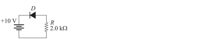 Figure 4
Refer to Figure 4. Assume the diode is a practical diode. The current in the diode will be
A)4.7 mA
B)5.7 mA
C)0 mA
D)0.2 mA
سؤال
C:\User 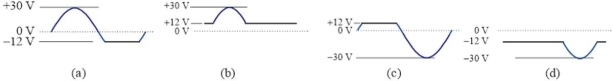 Figure 7
For questions 34, 35, and 36, assume ideal diodes
Which circuit in Figure 6 will produce the waveform in Figure 7(a)?
A)(a)
B)(b)
C)(c)
D)(d)
Figure 7For questions 34, 35, and 36, assume ideal diodes
Which circuit in Figure 6 will produce the waveform in Figure 7(a)?
A)(a)
B)(b)
C)(c)
D)(d)
سؤال
سؤال
سؤال
سؤال
 Figure 5
Refer to the circuit in Figure 5. The current in the load resistor is approximately
A)10 mA
B)5 mA
C)15 mA
D)2.5 mA
سؤال
سؤال
C:\User  Figure 7
For questions 34, 35, and 36, assume ideal diodes
Which circuit in Figure 6 will produce the waveform in Figure 7(b)?
A)(a)
B)(b)
C)(c)
D)(d)
Figure 7For questions 34, 35, and 36, assume ideal diodes
Which circuit in Figure 6 will produce the waveform in Figure 7(b)?
A)(a)
B)(b)
C)(c)
D)(d)

فتح الحزمة
قم بالتسجيل لفتح البطاقات في هذه المجموعة!
Unlock Deck
Unlock Deck
1/40
العب
ملء الشاشة (f)
Deck 2: Diodes and Applications
1
Figure 4Refer to Figure 4. Assume the diode is a practical diode. If the diode is reversed, the current in the diode will be
A)0 mA
B)4.7 mA
C)5.7 mA
D)0.2 mA
A
2
To convert the rms value of a sine wave to a peak value,
A)multiply the rms value by 0.637
B)divide the rms value by 0.707
C)multiply the rms value by 0.707
D)divide the rms value by 0.637
A)multiply the rms value by 0.637
B)divide the rms value by 0.707
C)multiply the rms value by 0.707
D)divide the rms value by 0.637
B
3
A voltage regulator compensates for changes in
A)temperature effects
B)load conditions
C)input voltage changes
D)all of the above
A)temperature effects
B)load conditions
C)input voltage changes
D)all of the above
D
4
Figure 8The maximum output voltage for the circuit in Figure 8 is approximately (Assume an ideal diode.)
A)Vp(in)
B)2Vp(in)
C)-Vp(in)
D)0 V
فتح الحزمة
افتح القفل للوصول البطاقات البالغ عددها 40 في هذه المجموعة.
فتح الحزمة
k this deck
5
Figure 5Refer to the circuit in Figure 5. The rms primary current is approximately
A)5.0 mA
B)500 mA
C)50 mA
D)0.5 mA
فتح الحزمة
افتح القفل للوصول البطاقات البالغ عددها 40 في هذه المجموعة.
فتح الحزمة
k this deck
6
Reverse current in a diode increases if
A)voltage increases
B)temperature increases
C)both A and B
D)none of the above
A)voltage increases
B)temperature increases
C)both A and B
D)none of the above
فتح الحزمة
افتح القفل للوصول البطاقات البالغ عددها 40 في هذه المجموعة.
فتح الحزمة
k this deck
7
The ripple frequency of a bridge rectifier is
A)equal to the input frequency
B)double the input frequency
C)four times the input frequency
D)half the input frequency
A)equal to the input frequency
B)double the input frequency
C)four times the input frequency
D)half the input frequency
فتح الحزمة
افتح القفل للوصول البطاقات البالغ عددها 40 في هذه المجموعة.
فتح الحزمة
k this deck
8
Figure 2Refer to Figure 2. The circuit that will produce a positive output is
A)(a)
B)(b)
C)(c)
D)(d)
فتح الحزمة
افتح القفل للوصول البطاقات البالغ عددها 40 في هذه المجموعة.
فتح الحزمة
k this deck
9
The ideal dc output voltage of a capacitor- input filter equals the
A)one- half of the peak of the rectified voltage
B)average value of the rectified voltage
C)peak value of the rectified voltage
D)rms value of the rectified voltage
A)one- half of the peak of the rectified voltage
B)average value of the rectified voltage
C)peak value of the rectified voltage
D)rms value of the rectified voltage
فتح الحزمة
افتح القفل للوصول البطاقات البالغ عددها 40 في هذه المجموعة.
فتح الحزمة
k this deck
10
Another name for a diode limiter circuit is
A)clipper
B)clamper
C)dc restorer
D)rectifier
A)clipper
B)clamper
C)dc restorer
D)rectifier
فتح الحزمة
افتح القفل للوصول البطاقات البالغ عددها 40 في هذه المجموعة.
فتح الحزمة
k this deck
11
A capacitor filtered half- wave rectifier has a ripple frequency that is
A)half that of the input frequency
B)twice that of the input frequency
C)the same as the input frequency
D)1.5 times the input frequency
A)half that of the input frequency
B)twice that of the input frequency
C)the same as the input frequency
D)1.5 times the input frequency
فتح الحزمة
افتح القفل للوصول البطاقات البالغ عددها 40 في هذه المجموعة.
فتح الحزمة
k this deck
12
Figure 1The circuit in Figure 1 is a
A)clamping circuit
B)bridge rectifier
C)center- tapped full- wave rectifier
D)half- wave rectifier
فتح الحزمة
افتح القفل للوصول البطاقات البالغ عددها 40 في هذه المجموعة.
فتح الحزمة
k this deck
13
Figure 5Refer to the circuit in Figure 5. The purpose of Rsurge is to
A)prevent load current from exceeding safe limits
B)prevent overheating the transformer
C)prevent an inrush of current that could damage diodes
D)all of the above
فتح الحزمة
افتح القفل للوصول البطاقات البالغ عددها 40 في هذه المجموعة.
فتح الحزمة
k this deck
14
Assume an ideal diode has a series 10 k▲ resistor and is reverse- biased with a 5.0 V source. The current in the diode is
A)0 mA
B)0.5 mA
C)2.0 mA
D)1.0 mA
A)0 mA
B)0.5 mA
C)2.0 mA
D)1.0 mA
فتح الحزمة
افتح القفل للوصول البطاقات البالغ عددها 40 في هذه المجموعة.
فتح الحزمة
k this deck
15
The VRRM specification on a manufacturer's data sheet is the same as the
A)forward voltage at maximum power
B)reverse breakdown voltage
C)forward voltage with 1 A of current
D)PIV
A)forward voltage at maximum power
B)reverse breakdown voltage
C)forward voltage with 1 A of current
D)PIV
فتح الحزمة
افتح القفل للوصول البطاقات البالغ عددها 40 في هذه المجموعة.
فتح الحزمة
k this deck
16
In a full wave bridge rectifier with a capacitor filter, assume a diode has opened. You expect to see
A)an increase in the ripple frequency
B)an increase in the ripple voltage
C)both A and B
D)none of the above
A)an increase in the ripple frequency
B)an increase in the ripple voltage
C)both A and B
D)none of the above
فتح الحزمة
افتح القفل للوصول البطاقات البالغ عددها 40 في هذه المجموعة.
فتح الحزمة
k this deck
17
Figure 8The circuit in Figure 8 is a
A)negative clipping circuit
B)negative clamping circuit
C)positive clipping circuit
D)positive clamping circuit
فتح الحزمة
افتح القفل للوصول البطاقات البالغ عددها 40 في هذه المجموعة.
فتح الحزمة
k this deck
18
The forward resistance of a diode is
A)constant
B)extremely high at all points
C)lower above the knee
D)lower below the knee
A)constant
B)extremely high at all points
C)lower above the knee
D)lower below the knee
فتح الحزمة
افتح القفل للوصول البطاقات البالغ عددها 40 في هذه المجموعة.
فتح الحزمة
k this deck
19
C:\User Figure 7
For questions 34, 35, and 36, assume ideal diodes
Which circuit in Figure 6 will produce the waveform in Figure 7(c)?
A)(a)
B)(b)
C)(c)
D)(d)
Figure 7For questions 34, 35, and 36, assume ideal diodes
Which circuit in Figure 6 will produce the waveform in Figure 7(c)?
A)(a)
B)(b)
C)(c)
D)(d)
فتح الحزمة
افتح القفل للوصول البطاقات البالغ عددها 40 في هذه المجموعة.
فتح الحزمة
k this deck
20
A capacitor filtered full- wave rectifier has a ripple frequency that is
A)1.5 times the input frequency
B)twice that of the input frequency
C)the same as the input frequency
D)half that of the input frequency
A)1.5 times the input frequency
B)twice that of the input frequency
C)the same as the input frequency
D)half that of the input frequency
فتح الحزمة
افتح القفل للوصول البطاقات البالغ عددها 40 في هذه المجموعة.
فتح الحزمة
k this deck
21
The anode of a diode is usually marked by a band, a tab, or some other feature.
فتح الحزمة
افتح القفل للوصول البطاقات البالغ عددها 40 في هذه المجموعة.
فتح الحزمة
k this deck
22
Figure 1For the circuit in Figure 1, assume ideal diodes. The peak inverse voltage is approximately
A)42 V
B)21 V
C)36 V
D)0 V
فتح الحزمة
افتح القفل للوصول البطاقات البالغ عددها 40 في هذه المجموعة.
فتح الحزمة
k this deck
23
Figure 1For the circuit in Figure 1, assume ideal diodes. The average voltage you should observe across RL is
A)13.5 V
B)19.2 V
C)9.6 V
D)27.0 V
فتح الحزمة
افتح القفل للوصول البطاقات البالغ عددها 40 في هذه المجموعة.
فتح الحزمة
k this deck
24
To forward bias a diode, the n- region is connected to the positive side of a voltage source.
فتح الحزمة
افتح القفل للوصول البطاقات البالغ عددها 40 في هذه المجموعة.
فتح الحزمة
k this deck
25
Figure 3For the circuit in Figure 3, assume practical diodes. The peak output voltage across the load is
A)16.3 V
B)17.7 V
C)7.8 V
D)9.2 V
فتح الحزمة
افتح القفل للوصول البطاقات البالغ عددها 40 في هذه المجموعة.
فتح الحزمة
k this deck
26
Figure 2Refer to Figure 2. The circuit that will produce a negative output is
A)(a)
B)(b)
C)(c)
D)(d)
فتح الحزمة
افتح القفل للوصول البطاقات البالغ عددها 40 في هذه المجموعة.
فتح الحزمة
k this deck
27
Figure 3For the circuit in Figure 3, assume a diode opens. As a result, the peak output voltage will be
A)larger
B)zero
C)approximately the same
D)halved
فتح الحزمة
افتح القفل للوصول البطاقات البالغ عددها 40 في هذه المجموعة.
فتح الحزمة
k this deck
28
An ideal diode is considered to have a small forward voltage drop across the junction.
فتح الحزمة
افتح القفل للوصول البطاقات البالغ عددها 40 في هذه المجموعة.
فتح الحزمة
k this deck
29
When a diode is forward- biased, the depletion region narrows.
فتح الحزمة
افتح القفل للوصول البطاقات البالغ عددها 40 في هذه المجموعة.
فتح الحزمة
k this deck
30
A silicon diode measures a very high value of resistance in one direction and very low resistance in the other. This indicates the diode is probably
A)good
B)open
C)shorted
A)good
B)open
C)shorted
فتح الحزمة
افتح القفل للوصول البطاقات البالغ عددها 40 في هذه المجموعة.
فتح الحزمة
k this deck
31
The component(s)immediately preceding the voltage regulation stage in a power supply is
A)a filter capacitor
B)the fuse
C)the transformer
D)the diodes
A)a filter capacitor
B)the fuse
C)the transformer
D)the diodes
فتح الحزمة
افتح القفل للوصول البطاقات البالغ عددها 40 في هذه المجموعة.
فتح الحزمة
k this deck
32
Figure 9The circuit in Figure 9 is a
A)clipping circuit
B)voltage doubler
C)voltage tripler
D)limiter circuit
فتح الحزمة
افتح القفل للوصول البطاقات البالغ عددها 40 في هذه المجموعة.
فتح الحزمة
k this deck
33
Figure 4Refer to Figure 4. Assume the diode is a practical diode. The current in the diode will be
A)4.7 mA
B)5.7 mA
C)0 mA
D)0.2 mA
فتح الحزمة
افتح القفل للوصول البطاقات البالغ عددها 40 في هذه المجموعة.
فتح الحزمة
k this deck
34
C:\User Figure 7
For questions 34, 35, and 36, assume ideal diodes
Which circuit in Figure 6 will produce the waveform in Figure 7(a)?
A)(a)
B)(b)
C)(c)
D)(d)
Figure 7For questions 34, 35, and 36, assume ideal diodes
Which circuit in Figure 6 will produce the waveform in Figure 7(a)?
A)(a)
B)(b)
C)(c)
D)(d)
فتح الحزمة
افتح القفل للوصول البطاقات البالغ عددها 40 في هذه المجموعة.
فتح الحزمة
k this deck
35
When a diode is reverse- biased, the current is normally extremely small.
فتح الحزمة
افتح القفل للوصول البطاقات البالغ عددها 40 في هذه المجموعة.
فتح الحزمة
k this deck
36
Assume an ideal diode has a series 10 k▲ resistor and is forward- biased with a 20 V source. The current in the diode is
A)2.0 mA
B)0 mA
C)1.0 mA
D)0.5 mA
A)2.0 mA
B)0 mA
C)1.0 mA
D)0.5 mA
فتح الحزمة
افتح القفل للوصول البطاقات البالغ عددها 40 في هذه المجموعة.
فتح الحزمة
k this deck
37
For a forward- biased diode, as temperature increases, forward current also increases.
فتح الحزمة
افتح القفل للوصول البطاقات البالغ عددها 40 في هذه المجموعة.
فتح الحزمة
k this deck
38
Figure 5Refer to the circuit in Figure 5. The current in the load resistor is approximately
A)10 mA
B)5 mA
C)15 mA
D)2.5 mA
فتح الحزمة
افتح القفل للوصول البطاقات البالغ عددها 40 في هذه المجموعة.
فتح الحزمة
k this deck
39
Dynamic resistance is the same as linear resistance.
فتح الحزمة
افتح القفل للوصول البطاقات البالغ عددها 40 في هذه المجموعة.
فتح الحزمة
k this deck
40
C:\User Figure 7
For questions 34, 35, and 36, assume ideal diodes
Which circuit in Figure 6 will produce the waveform in Figure 7(b)?
A)(a)
B)(b)
C)(c)
D)(d)
Figure 7For questions 34, 35, and 36, assume ideal diodes
Which circuit in Figure 6 will produce the waveform in Figure 7(b)?
A)(a)
B)(b)
C)(c)
D)(d)
فتح الحزمة
افتح القفل للوصول البطاقات البالغ عددها 40 في هذه المجموعة.
فتح الحزمة
k this deck
فتح الحزمة
افتح القفل للوصول البطاقات البالغ عددها 40 في هذه المجموعة.


