Deck 41: Systems Troubleshooting
ملء الشاشة (f)
سؤال
In Fig. 41-18, a +5-V signal is applied to the input of the transistor. The LED does not light. A measurement at the collector of the transistor reveals a voltage of +5 V. What are the most likely problems 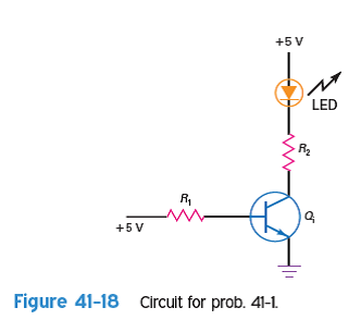
سؤال
سؤال
In Fig. 41-19, the circuit is not performing as it should. This schematic is all you have. Determine what the output is supposed to be. Measuring the output, you get a dc voltage value of -12 V. What is the problem 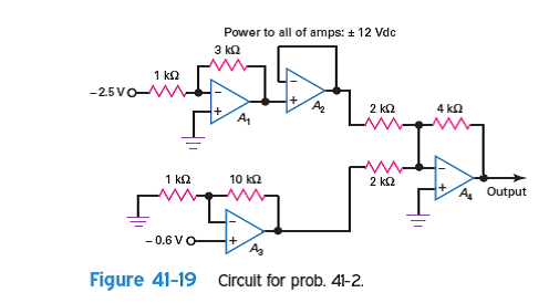
سؤال
سؤال
Consider the circuit of Fig. 41-20. What is the desired output If the output is a series of 60-Hzpulses across D 2 , what is the most likely problem 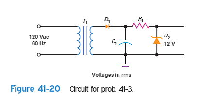
سؤال
سؤال
In Fig. 41-21, the circuits are operating properly except for a 500-kHz signal riding on the 8-V dc output. What may be the problem 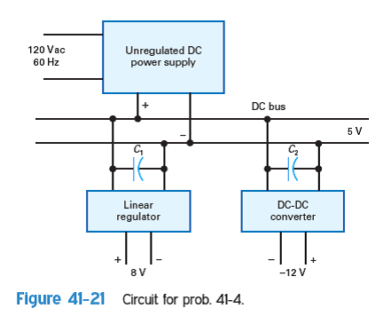
سؤال
سؤال
سؤال
سؤال
سؤال
سؤال
In the garage door example given in Fig. 41-14, the door will open but not close. What may be the problem 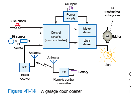
سؤال
سؤال
In the home entertainment center of Fig. 41-17,the TV set is working but you cannot play a movie DVD. Give several reasons why you cannot do this. 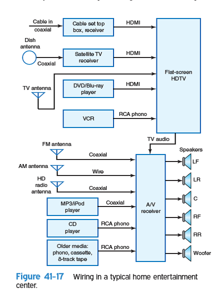
سؤال
سؤال
The automatic lawn sprinkler system, shown in Fig. 41-22, has four zones of operation. Water sprinkler heads in each zone turn on in sequence for a specific amount of time. 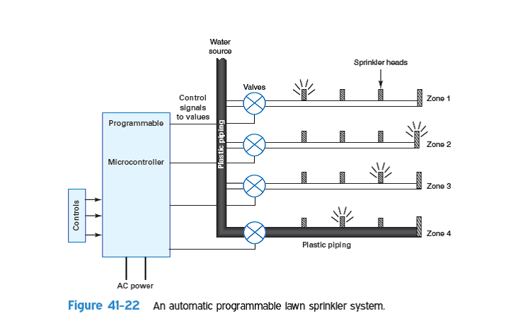
سؤال
سؤال
سؤال
سؤال
سؤال
سؤال
سؤال
سؤال
سؤال
سؤال
In Fig. 41-8, the input to stage 1 is good and the output from stage 4 is not correct. The problem lies in
A) stage 1.
B) stage 2.
C) stage 4.
D) any of the stages.
A) stage 1.
B) stage 2.
C) stage 4.
D) any of the stages.
سؤال
In Fig. 41-8, there is no output from stage 1. The problem is
A) a defective stage 1.
B) no input signal.
C) either a or b.
D) not having enough information to determine.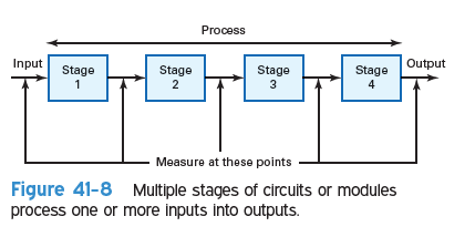
A) a defective stage 1.
B) no input signal.
C) either a or b.
D) not having enough information to determine.
سؤال
سؤال
سؤال
سؤال
سؤال
سؤال

فتح الحزمة
قم بالتسجيل لفتح البطاقات في هذه المجموعة!
Unlock Deck
Unlock Deck
1/34
العب
ملء الشاشة (f)
Deck 41: Systems Troubleshooting
1
In Fig. 41-18, a +5-V signal is applied to the input of the transistor. The LED does not light. A measurement at the collector of the transistor reveals a voltage of +5 V. What are the most likely problems
The proper circuit operation is that when the input of the transistor is +5 V the transistor conducts and the LED glows. When the input of the transistor is low then the transistor is opened and the LED doesn't glow.
Even when the input of the transistor is +5 V and if the LED doesn't glow then the possible errors are
• The transistor failed.
• The resistor must be opened.
• The resistor must be opened.
• The LED failed.
Even when the input of the transistor is +5 V and if the LED doesn't glow then the possible errors are
• The transistor
failed.• The resistor
must be opened.• The resistor
must be opened.• The LED failed.
2
The most common job of an electronics technician is
A) design.
B) circuit analysis.
C) testing.
D) troubleshooting.
A) design.
B) circuit analysis.
C) testing.
D) troubleshooting.
Troubleshooting is a science and art of finding the errors or failures in the circuits, equipment and electronic systems. It relies mostly on basic knowledge on the equipment and components.
Design, circuit analysis and testing need more technical knowledge, whereas the troubleshooting requires basic knowledge on the equipment. Hence, most common job for a technician is troubleshooting.
Thus, the correct option is .
.
Design, circuit analysis and testing need more technical knowledge, whereas the troubleshooting requires basic knowledge on the equipment. Hence, most common job for a technician is troubleshooting.
Thus, the correct option is
. 3
In Fig. 41-19, the circuit is not performing as it should. This schematic is all you have. Determine what the output is supposed to be. Measuring the output, you get a dc voltage value of -12 V. What is the problem
Consider the circuit in the Figure 41-19,
• The output of the op-amp is
is  • The output of the op-amp
  is
is  since it is a positive unit gain amplifier.
• The output of the op-amp is
is  • The
• The  resistors are in parallel and forms a
  .
.
• The input to the resistor formed is
  • Total output is
  Hence the output that is supposed to be is
  It is given that the output measured was
  the problems can be as follows
• The op-amps are malfunctioned.
• The feedback resistors may offer more resistance.
• The input resistors may offer less resistance.
• The output of the op-amp
is • The output of the op-amp is since it is a positive unit gain amplifier.• The output of the op-amp
is • The resistors are in parallel and forms a .• The input to the
resistor formed is • Total output is Hence the output that is supposed to be is It is given that the output measured was the problems can be as follows• The op-amps are malfunctioned.
• The feedback resistors may offer more resistance.
• The input resistors may offer less resistance.
4
Which test instrument presents its output in the frequency domain
A) Spectrum analyzer.
B) Oscilloscope.
C) Multimeter.
D) Logic analyzer.
A) Spectrum analyzer.
B) Oscilloscope.
C) Multimeter.
D) Logic analyzer.
فتح الحزمة
افتح القفل للوصول البطاقات البالغ عددها 34 في هذه المجموعة.
فتح الحزمة
k this deck
5
Consider the circuit of Fig. 41-20. What is the desired output If the output is a series of 60-Hzpulses across D 2 , what is the most likely problem
فتح الحزمة
افتح القفل للوصول البطاقات البالغ عددها 34 في هذه المجموعة.
فتح الحزمة
k this deck
6
Which test instrument presents its output in the time domain
A) Spectrum analyzer.
B) Oscilloscope.
C) Multimeter.
D) Signal generator.
A) Spectrum analyzer.
B) Oscilloscope.
C) Multimeter.
D) Signal generator.
فتح الحزمة
افتح القفل للوصول البطاقات البالغ عددها 34 في هذه المجموعة.
فتح الحزمة
k this deck
7
In Fig. 41-21, the circuits are operating properly except for a 500-kHz signal riding on the 8-V dc output. What may be the problem
فتح الحزمة
افتح القفل للوصول البطاقات البالغ عددها 34 في هذه المجموعة.
فتح الحزمة
k this deck
8
The spectrum analyzer shows what characteristic on the vertical scale of the output
A) Voltage.
B) Current.
C) Power.
D) Impedance.
A) Voltage.
B) Current.
C) Power.
D) Impedance.
فتح الحزمة
افتح القفل للوصول البطاقات البالغ عددها 34 في هذه المجموعة.
فتح الحزمة
k this deck
9
One of the PC board modules in a piece of equipment has failed. A replacement board costs $85. There pair can be made by just plugging in a new board. On the other hand, a technician can repair the board in an estimated 2 hours if the $6 defective IC is available. The technician cost is $45 per hour. What is the recommended solution
فتح الحزمة
افتح القفل للوصول البطاقات البالغ عددها 34 في هذه المجموعة.
فتح الحزمة
k this deck
10
A signal generator that produces sine, square, and triangular waves from about 1 Hz to 6 MHz is called a(n)
A) RF signal generator.
B) AWG.
C) function generator.
D) frequency synthesizer.
A) RF signal generator.
B) AWG.
C) function generator.
D) frequency synthesizer.
فتح الحزمة
افتح القفل للوصول البطاقات البالغ عددها 34 في هذه المجموعة.
فتح الحزمة
k this deck
11
If documentation is not available for the device or system you are troubleshooting, what may be a way to get that
فتح الحزمة
افتح القفل للوصول البطاقات البالغ عددها 34 في هذه المجموعة.
فتح الحزمة
k this deck
12
Most modern test instruments are
A) analog.
B) digital.
A) analog.
B) digital.
فتح الحزمة
افتح القفل للوصول البطاقات البالغ عددها 34 في هذه المجموعة.
فتح الحزمة
k this deck
13
In the garage door example given in Fig. 41-14, the door will open but not close. What may be the problem
فتح الحزمة
افتح القفل للوصول البطاقات البالغ عددها 34 في هذه المجموعة.
فتح الحزمة
k this deck
14
What is the first process that an input signal encounters in a modern test instrument
A) Filtering.
B) Frequency conversion.
C) Digital-to-analog conversion.
D) Analog-to-digital conversion.
A) Filtering.
B) Frequency conversion.
C) Digital-to-analog conversion.
D) Analog-to-digital conversion.
فتح الحزمة
افتح القفل للوصول البطاقات البالغ عددها 34 في هذه المجموعة.
فتح الحزمة
k this deck
15
In the home entertainment center of Fig. 41-17,the TV set is working but you cannot play a movie DVD. Give several reasons why you cannot do this.
فتح الحزمة
افتح القفل للوصول البطاقات البالغ عددها 34 في هذه المجموعة.
فتح الحزمة
k this deck
16
In a modern test instrument, how is the measurement actually made
A) An embedded microcontroller processes the digital input.
B) Analog circuits interpret the signal and display it.
C) The signal is directly displayed for the user to measure.
D) Level comparators decide the signal amplitude.
A) An embedded microcontroller processes the digital input.
B) Analog circuits interpret the signal and display it.
C) The signal is directly displayed for the user to measure.
D) Level comparators decide the signal amplitude.
فتح الحزمة
افتح القفل للوصول البطاقات البالغ عددها 34 في هذه المجموعة.
فتح الحزمة
k this deck
17
The automatic lawn sprinkler system, shown in Fig. 41-22, has four zones of operation. Water sprinkler heads in each zone turn on in sequence for a specific amount of time.
فتح الحزمة
افتح القفل للوصول البطاقات البالغ عددها 34 في هذه المجموعة.
فتح الحزمة
k this deck
18
A virtual instrument generally uses what to process the input signal
A) Embedded controller.
B) Personal or laptop computer.
C) An FPGA or DSP chip.
D) No processing is done.
A) Embedded controller.
B) Personal or laptop computer.
C) An FPGA or DSP chip.
D) No processing is done.
فتح الحزمة
افتح القفل للوصول البطاقات البالغ عددها 34 في هذه المجموعة.
فتح الحزمة
k this deck
19
What makes the measurement in a virtual instrument
A) Hardware.
B) Software.
A) Hardware.
B) Software.
فتح الحزمة
افتح القفل للوصول البطاقات البالغ عددها 34 في هذه المجموعة.
فتح الحزمة
k this deck
20
What is the name of the software that is used to create virtual instruments
A) The C language.
B) Java.
C) LabVIEW.
D) MathCAD.
A) The C language.
B) Java.
C) LabVIEW.
D) MathCAD.
فتح الحزمة
افتح القفل للوصول البطاقات البالغ عددها 34 في هذه المجموعة.
فتح الحزمة
k this deck
21
Which of the following is not part of an AWG
A) DAC.
B) Frequency synthesizer.
C) Memory.
D) ADC.
A) DAC.
B) Frequency synthesizer.
C) Memory.
D) ADC.
فتح الحزمة
افتح القفل للوصول البطاقات البالغ عددها 34 في هذه المجموعة.
فتح الحزمة
k this deck
22
It is often more economical and faster to replace a product or subassembly than to repair it.
فتح الحزمة
افتح القفل للوصول البطاقات البالغ عددها 34 في هذه المجموعة.
فتح الحزمة
k this deck
23
The first step in most troubleshooting processes is to
A) isolate the problem.
B) do a visual inspection.
C) verify that the problem exists.
D) check for power.
A) isolate the problem.
B) do a visual inspection.
C) verify that the problem exists.
D) check for power.
فتح الحزمة
افتح القفل للوصول البطاقات البالغ عددها 34 في هذه المجموعة.
فتح الحزمة
k this deck
24
You should not attempt to troubleshoot a piece of equipment without
A) the documentation.
B) an oscilloscope.
C) multimeter.
D) training.
A) the documentation.
B) an oscilloscope.
C) multimeter.
D) training.
فتح الحزمة
افتح القفل للوصول البطاقات البالغ عددها 34 في هذه المجموعة.
فتح الحزمة
k this deck
25
Electronic components are generally more likely to fail than mechanical components.
فتح الحزمة
افتح القفل للوصول البطاقات البالغ عددها 34 في هذه المجموعة.
فتح الحزمة
k this deck
26
A good first step in troubleshooting a circuit is to
A) test all transistors.
B) check for overheated ICs.
C) verify that the correct dc voltages are present.
D) begin signal tracing.
A) test all transistors.
B) check for overheated ICs.
C) verify that the correct dc voltages are present.
D) begin signal tracing.
فتح الحزمة
افتح القفل للوصول البطاقات البالغ عددها 34 في هذه المجموعة.
فتح الحزمة
k this deck
27
In Fig. 41-8, the input to stage 1 is good and the output from stage 4 is not correct. The problem lies in
A) stage 1.
B) stage 2.
C) stage 4.
D) any of the stages.
A) stage 1.
B) stage 2.
C) stage 4.
D) any of the stages.
فتح الحزمة
افتح القفل للوصول البطاقات البالغ عددها 34 في هذه المجموعة.
فتح الحزمة
k this deck
28
In Fig. 41-8, there is no output from stage 1. The problem is
A) a defective stage 1.
B) no input signal.
C) either a or b.
D) not having enough information to determine.
A) a defective stage 1.
B) no input signal.
C) either a or b.
D) not having enough information to determine.
فتح الحزمة
افتح القفل للوصول البطاقات البالغ عددها 34 في هذه المجموعة.
فتح الحزمة
k this deck
29
Most detailed troubleshooting should not begin unless
A) you have the documentation.
B) you are familiar with the equipment.
C) you have been trained on the equipment.
D) all of the above.
A) you have the documentation.
B) you are familiar with the equipment.
C) you have been trained on the equipment.
D) all of the above.
فتح الحزمة
افتح القفل للوصول البطاقات البالغ عددها 34 في هذه المجموعة.
فتح الحزمة
k this deck
30
The most likely component to fail in a system is a(n)
A) diode.
B) integrated circuit.
C) capacitor.
D) resistor.
A) diode.
B) integrated circuit.
C) capacitor.
D) resistor.
فتح الحزمة
افتح القفل للوصول البطاقات البالغ عددها 34 في هذه المجموعة.
فتح الحزمة
k this deck
31
Which is often the primary goal of troubleshooting a piece of equipment
A) Low cost.
B) Minimum downtime.
C) Continued long product life.
D) No need for experienced repairers.
A) Low cost.
B) Minimum downtime.
C) Continued long product life.
D) No need for experienced repairers.
فتح الحزمة
افتح القفل للوصول البطاقات البالغ عددها 34 في هذه المجموعة.
فتح الحزمة
k this deck
32
For complex digital circuit troubleshooting, the best instrument is probably the
A) oscilloscope.
B) spectrum analyzer.
C) logic analyzer.
D) signal generator.
A) oscilloscope.
B) spectrum analyzer.
C) logic analyzer.
D) signal generator.
فتح الحزمة
افتح القفل للوصول البطاقات البالغ عددها 34 في هذه المجموعة.
فتح الحزمة
k this deck
33
In systems troubleshooting, it is best to approach the problem with
A) block diagram analysis.
B) schematic diagram analysis.
C) testing all individual components.
D) replacement of complete subsystems.
A) block diagram analysis.
B) schematic diagram analysis.
C) testing all individual components.
D) replacement of complete subsystems.
فتح الحزمة
افتح القفل للوصول البطاقات البالغ عددها 34 في هذه المجموعة.
فتح الحزمة
k this deck
34
A quick but expensive and often effective troubleshooting approach is
A) complete unit replacement.
B) component or module substitution.
C) signal tracing to the component level.
D) dc voltage measurement.
A) complete unit replacement.
B) component or module substitution.
C) signal tracing to the component level.
D) dc voltage measurement.
فتح الحزمة
افتح القفل للوصول البطاقات البالغ عددها 34 في هذه المجموعة.
فتح الحزمة
k this deck
فتح الحزمة
افتح القفل للوصول البطاقات البالغ عددها 34 في هذه المجموعة.


