Deck 6: Internal Effects in Bars, Shafts, Beams and Frames
ملء الشاشة (f)
سؤال
simple beam AB with an overhang BC is loaded as shown in the figure. The bending moment at the midspan of AB is approximately: 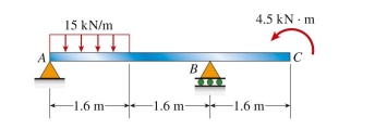
(A) 8 kN ∙ m
(B) 12 kN ∙ m
(C) 17 kN ∙ m
(D) 21 kN ∙ m
(A) 8 kN ∙ m
(B) 12 kN ∙ m
(C) 17 kN ∙ m
(D) 21 kN ∙ m
سؤال
cantilever beam is loaded as shown in the figure. The bending moment at 0.5 m from the support is approximately: 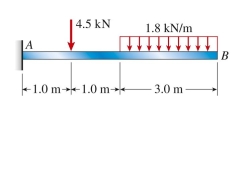
(A) 12.7 kN ∙ m
(B) 14.2 kN ∙ m
(C) 16.1 kN ∙ m
(D) 18.5 kN ∙ m
(A) 12.7 kN ∙ m
(B) 14.2 kN ∙ m
(C) 16.1 kN ∙ m
(D) 18.5 kN ∙ m
سؤال
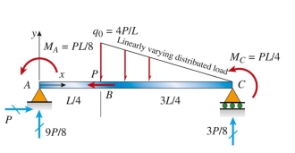
The simply supported beam ABC shown below is acted upon by applied axial force P at B; by linearly varying distributed load q on BC; and by applied moments  . Reaction forces are given in the figure
In terms of load variable P. The axial force (N), shear (V), and bending moment (M) at mid-span are (in terms
Of variables L and P):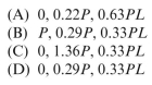
 Stresses and strain
. Reaction forces are given in the figureIn terms of load variable P. The axial force (N), shear (V), and bending moment (M) at mid-span are (in terms
Of variables L and P):
Stresses and strain سؤال
T-shaped simple beam has a cable with force P anchored at B and passing over a pulley at E, as shown in the figure. The bending moment just left of C is 1.25 kN ∙ m. The cable force P is approximately: 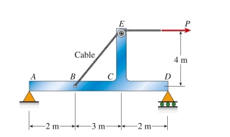
(A) 2.7 kN
(B) 3.9 kN
(C) 4.5 kN
(D) 6.2 kN
(A) 2.7 kN
(B) 3.9 kN
(C) 4.5 kN
(D) 6.2 kN
سؤال
simply supported beam is loaded as shown in the figure. The bending moment at point C is approximately: 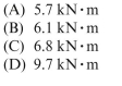
سؤال
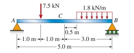
simple beam (L 5 9 m) with attached bracket BDE has force P 5 5 kN applied downward at E. The bending moment just right of  is approximately:
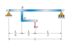
(A) 6 N ∙ m
(B) 10 N ∙ m
(C) 19 N ∙ m
(D) 22 N ∙ m
is approximately: (A) 6 N ∙ m
(B) 10 N ∙ m
(C) 19 N ∙ m
(D) 22 N ∙ m
سؤال
Reaction forces are given in the figure below for beam ABCDE. The bending moment at C (in kN ∙ m) is: 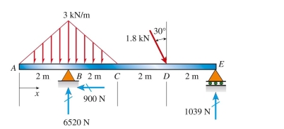
(A) 0.84 kN ∙ m
(B) 0.96 kN ∙ m
(C) 1.04 kN ∙ m
(D) 1.36 kN ∙ m
(A) 0.84 kN ∙ m
(B) 0.96 kN ∙ m
(C) 1.04 kN ∙ m
(D) 1.36 kN ∙ m
سؤال
simply supported beam with proportional loading (P 5 4.1 kN) has span length L 5 5 m. Load P is 1.2 m from support A and load 2P is 1.5 m from support B. The bending moment just left of load 2P is approximately: 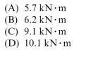
سؤال
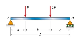
L-shaped beam is loaded as shown in the figure. The bending moment at the midpoint of span AB is approximately: 
(A) 6.8 kN ∙ m
(B) 10.1 kN ∙ m
(C) 12.3 kN ∙ m
(D) 15.5 kN ∙ m
(A) 6.8 kN ∙ m
(B) 10.1 kN ∙ m
(C) 12.3 kN ∙ m
(D) 15.5 kN ∙ m
سؤال
cable with known tension force T is anchored at C and passes over a frictionless drum (see figure). The pin force components 
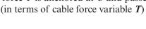 or the pin connection at B are:
  T
T 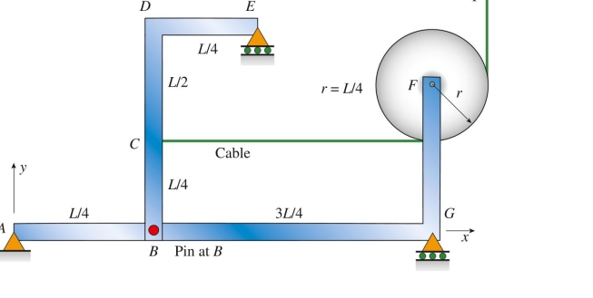
or the pin connection at B are: T 
فتح الحزمة
قم بالتسجيل لفتح البطاقات في هذه المجموعة!
Unlock Deck
Unlock Deck
1/10
العب
ملء الشاشة (f)
Deck 6: Internal Effects in Bars, Shafts, Beams and Frames
1
simple beam AB with an overhang BC is loaded as shown in the figure. The bending moment at the midspan of AB is approximately:
(A) 8 kN ∙ m
(B) 12 kN ∙ m
(C) 17 kN ∙ m
(D) 21 kN ∙ m
(A) 8 kN ∙ m
(B) 12 kN ∙ m
(C) 17 kN ∙ m
(D) 21 kN ∙ m
B
2
cantilever beam is loaded as shown in the figure. The bending moment at 0.5 m from the support is approximately:
(A) 12.7 kN ∙ m
(B) 14.2 kN ∙ m
(C) 16.1 kN ∙ m
(D) 18.5 kN ∙ m
(A) 12.7 kN ∙ m
(B) 14.2 kN ∙ m
(C) 16.1 kN ∙ m
(D) 18.5 kN ∙ m
D
3
The simply supported beam ABC shown below is acted upon by applied axial force P at B; by linearly varying distributed load q on BC; and by applied moments . Reaction forces are given in the figure
In terms of load variable P. The axial force (N), shear (V), and bending moment (M) at mid-span are (in terms
Of variables L and P): Stresses and strain
. Reaction forces are given in the figureIn terms of load variable P. The axial force (N), shear (V), and bending moment (M) at mid-span are (in terms
Of variables L and P):
Stresses and strainD
4
T-shaped simple beam has a cable with force P anchored at B and passing over a pulley at E, as shown in the figure. The bending moment just left of C is 1.25 kN ∙ m. The cable force P is approximately:
(A) 2.7 kN
(B) 3.9 kN
(C) 4.5 kN
(D) 6.2 kN
(A) 2.7 kN
(B) 3.9 kN
(C) 4.5 kN
(D) 6.2 kN
فتح الحزمة
افتح القفل للوصول البطاقات البالغ عددها 10 في هذه المجموعة.
فتح الحزمة
k this deck
5
simply supported beam is loaded as shown in the figure. The bending moment at point C is approximately:
فتح الحزمة
افتح القفل للوصول البطاقات البالغ عددها 10 في هذه المجموعة.
فتح الحزمة
k this deck
6
simple beam (L 5 9 m) with attached bracket BDE has force P 5 5 kN applied downward at E. The bending moment just right of is approximately:
(A) 6 N ∙ m
(B) 10 N ∙ m
(C) 19 N ∙ m
(D) 22 N ∙ m
is approximately: (A) 6 N ∙ m
(B) 10 N ∙ m
(C) 19 N ∙ m
(D) 22 N ∙ m
فتح الحزمة
افتح القفل للوصول البطاقات البالغ عددها 10 في هذه المجموعة.
فتح الحزمة
k this deck
7
Reaction forces are given in the figure below for beam ABCDE. The bending moment at C (in kN ∙ m) is:
(A) 0.84 kN ∙ m
(B) 0.96 kN ∙ m
(C) 1.04 kN ∙ m
(D) 1.36 kN ∙ m
(A) 0.84 kN ∙ m
(B) 0.96 kN ∙ m
(C) 1.04 kN ∙ m
(D) 1.36 kN ∙ m
فتح الحزمة
افتح القفل للوصول البطاقات البالغ عددها 10 في هذه المجموعة.
فتح الحزمة
k this deck
8
simply supported beam with proportional loading (P 5 4.1 kN) has span length L 5 5 m. Load P is 1.2 m from support A and load 2P is 1.5 m from support B. The bending moment just left of load 2P is approximately:
فتح الحزمة
افتح القفل للوصول البطاقات البالغ عددها 10 في هذه المجموعة.
فتح الحزمة
k this deck
9
L-shaped beam is loaded as shown in the figure. The bending moment at the midpoint of span AB is approximately:
(A) 6.8 kN ∙ m
(B) 10.1 kN ∙ m
(C) 12.3 kN ∙ m
(D) 15.5 kN ∙ m
(A) 6.8 kN ∙ m
(B) 10.1 kN ∙ m
(C) 12.3 kN ∙ m
(D) 15.5 kN ∙ m
فتح الحزمة
افتح القفل للوصول البطاقات البالغ عددها 10 في هذه المجموعة.
فتح الحزمة
k this deck
10
cable with known tension force T is anchored at C and passes over a frictionless drum (see figure). The pin force components or the pin connection at B are: T
or the pin connection at B are: T فتح الحزمة
افتح القفل للوصول البطاقات البالغ عددها 10 في هذه المجموعة.
فتح الحزمة
k this deck
فتح الحزمة
افتح القفل للوصول البطاقات البالغ عددها 10 في هذه المجموعة.


