For the block diagram of the input module shown,Section #1 represents the ____ and #2 the ____ 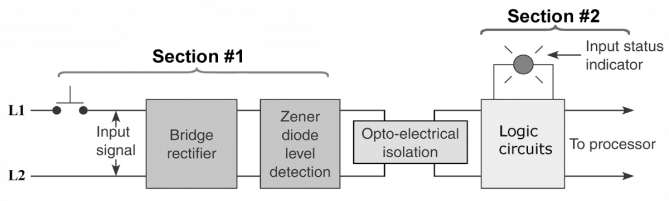
A) AC,DC.
B) DC,AC.
C) power,logic.
D) logic,power.
Correct Answer:
Verified
Q43: _ memory is used by the PLC's
Q48: Which of the following is not a
Q54: The Allen-Bradley SLC-500 address I:2/4 refers to
Q55: The Allen-Bradley SLC-500 address O:3/0 refers to
Q56: The schematic diagram shown is that of
Q57: The PLC chassis comes in different sizes
Q59: The purpose of the optical isolator is
Q61: High-density I/O modules:
A)may have up to 64
Q62: The current sourcing sensor shown must be
Q70: Discrete I/O modules can be classified as
A)bit
Unlock this Answer For Free Now!
View this answer and more for free by performing one of the following actions

Scan the QR code to install the App and get 2 free unlocks

Unlock quizzes for free by uploading documents