The schematic diagram shown is that of a(n) : 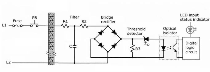
A) discrete output module.
B) analog output module.
C) discrete input module.
D) analog input module.
Correct Answer:
Verified
Q42: The I/O system provides an interface between
A)input
Q44: The purpose of the filter section is
Q46: For the I/O module shown,the arrows point
Q47: For the block diagram of the output
Q47: In event of a power interruption, a(an)
Q48: Which of the following is not a
Q49: The purpose of the LED indicator is
Q50: The purpose of the zener diode (ZD)is
Q51: The most common form of memory used
Q56: Status indicators are provided on each output
Unlock this Answer For Free Now!
View this answer and more for free by performing one of the following actions

Scan the QR code to install the App and get 2 free unlocks

Unlock quizzes for free by uploading documents