The schematic diagram of Figure 2-6 is an example of how a PLC output module is connected to: 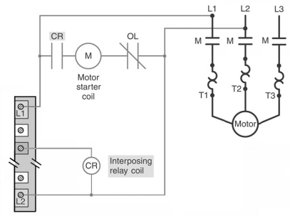
A) isolate the load from the controller.
B) control a high resistance load.
C) vary the speed of a motor.
D) control a high current load.
Correct Answer:
Verified
Q61: The main element of an analog output
Q64: The _ of an analog I/O module
Q65: The processor module of the PLC is
Q66: A _ module is used to establish
Q73: For the thermocouple analog input module shown,shielded
Q73: Which of the following special I/O modules
Q75: The thermocouple shown is a: 
Q78: Which of the following devices can be
Q79: The purpose of the triac switch is
Q81: Electronic components found in PLC modules:
A)are not
Unlock this Answer For Free Now!
View this answer and more for free by performing one of the following actions

Scan the QR code to install the App and get 2 free unlocks

Unlock quizzes for free by uploading documents