
Basic Engineering Circuit Analysis 11th Edition by David Irwin ,Robert Nelms
النسخة 11الرقم المعياري الدولي: 978-1118539293Basic Engineering Circuit Analysis 11th Edition by David Irwin ,Robert Nelms
النسخة 11الرقم المعياري الدولي: 978-1118539293 تمرين 16
The currents in the magnetically coupled inductors shown in Fig. P10.39 are known to be
i 1 ( t ) = 8 cos (377 t 20°) mA and
i 2 ( t ) = 4 cos (377 t 50°) mA. The inductor values are L 1 = 2 H, L 2 = 1 H, and k = 0.6. Determine v 1 ( t ) and v 2 ( t ).
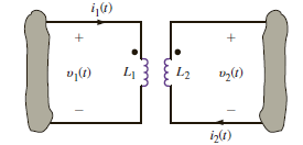
Figure P10.39
i 1 ( t ) = 8 cos (377 t 20°) mA and
i 2 ( t ) = 4 cos (377 t 50°) mA. The inductor values are L 1 = 2 H, L 2 = 1 H, and k = 0.6. Determine v 1 ( t ) and v 2 ( t ).
Figure P10.39
التوضيح موثّق
موثّق
Refer to Figure P10.37 from the text boo...
Basic Engineering Circuit Analysis 11th Edition by David Irwin ,Robert Nelms
لماذا لم يعجبك هذا التمرين؟
أخرى 8 أحرف كحد أدنى و 255 حرفاً كحد أقصى
حرف 255


