Deck 10: Amplifier Frequency Response
Full screen (f)
Question
Question
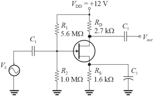 Figure 2 IGSS (max)= 100 pA. VGS = -2.4 V
Refer to Figure 2. Assume RS is the only resistance "seen" by C2. The value of C2 that has a lower cutoff frequency of approximately 20 Hz is
A)5.0 µF
B)50 µF
C)22 µF
D)1.0 µF
Question
Question
 Figure 2 IGSS (max)= 100 pA. VGS = -2.4 V
Refer to Figure 2. The value of C1 that has a lower cutoff frequency of approximately 20 Hz is
A)0.10 µF
B)10 nF
C)1 nF
D)1.0 µF
Question
 Figure 3
Refer to Figure 3. The value of C2 that will result in a lower cutoff frequency of 40 Hz is
A)0.4 µF
B)0.2 µF
C)0.8 µF
D)2.0 µF
Question
Question
Question
Question
Question
Question
Question
 Figure 1 Assume re' = 15 ▲.
Refer to Figure 1. The cutoff frequency due to C1 is
A)23 Hz
B)13 Hz
C)40 Hz
D)7.2 Hz
Question
Question
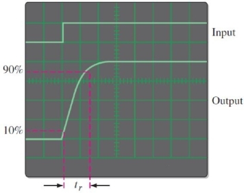 Figure 5. The sec/div control is set to 0.05 µS/div.
Refer to Figure 5. From the information given, the fcu is approximately
A)7.0 MHz
B)4.7 MHz
C)13.4 MHz
D)20 MHz
Question
 Figure 4 Response of an amplifier
Refer to Figure 4. The Bode plotter is a computer tool that
A)shows amplitude as a function of frequency
B)shows amplitude as a function of time
C)both A and B
D)none of the above
Question
Question
 Figure 1 Assume re' = 15 ▲.
Refer to Figure 1. Rin is approximately
A)10 k▲
B)5.7 k▲
C)3.2 k▲
D)1.8 k▲
Question
 Figure 1 Assume re' = 15 ▲.
Refer to Figure 1. If the RE1 is changed to a 33 ▲ resistor, the upper cutoff frequency
A)increases
B)decreases
C)is unaffected
Question
Question
Question
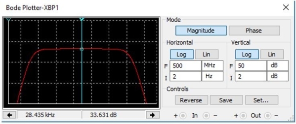 Figure 4 Response of an amplifier
Refer to Figure 4. The amplifier's frequency response indicates the midrange gain is 33.6 dB. Expressed as regular gain, this is approximately
A)31
B)70
C)24
D)48
Question
Question
Question
Question
Question
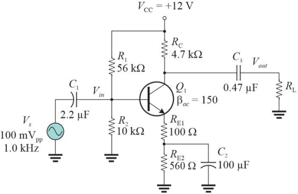 Figure 1 Assume re' = 15 ▲.
Refer to Figure 1. Assume that Cbc = 6 pF and RL= 27 k▲. The Miller input capacitance due to Cbc is
A)168 pF
B)7.0 pF
C)216 pF
D)49 pF
Question
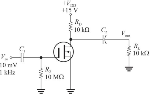 Figure 3
Refer to Figure 3. Assume the unloaded gain of the amplifier is 10. The ac equivalent Thevenin circuit looking back to the drain from C2 is
A)Vth = 50 mV; Rth =5.0 k▲
B)Vth = 100 mV; Rth =5.0 k▲
C)Vth = 100 mV; Rth =10 k▲
D)Vth = 50 mV; Rth =10 k▲
Question
Figure 1 Assume re' = 15 ▲.Refer to Figure 1. What value of RL will produce a cutoff frequency due to C3 of 25 Hz?
A)19 k▲
B)8.8 k▲
C)24 k▲
D)14 k▲
Question
Question
Question
Question
Question

Unlock Deck
Sign up to unlock the cards in this deck!
Unlock Deck
Unlock Deck
1/33
Play
Full screen (f)
Deck 10: Amplifier Frequency Response
1
The capacitor that determines the dominant lower cutoff frequency is
A)whichever capacitor has the highest fcl
B)the input coupling capacitor
C)the bypass capacitor
D)the internal transistor capacitance
A)whichever capacitor has the highest fcl
B)the input coupling capacitor
C)the bypass capacitor
D)the internal transistor capacitance
A
2
Figure 2 IGSS (max)= 100 pA. VGS = -2.4 VRefer to Figure 2. Assume RS is the only resistance "seen" by C2. The value of C2 that has a lower cutoff frequency of approximately 20 Hz is
A)5.0 µF
B)50 µF
C)22 µF
D)1.0 µF
A
3
When each amplifier stage in a two- stage amplifier has equal dominant upper critical frequencies, the overall dominant frequency is equal to
A)less than the dominant frequency of one stage
B)the dominant frequency of one stage
C)twice the dominant frequency of one stage
D)none of the above
A)less than the dominant frequency of one stage
B)the dominant frequency of one stage
C)twice the dominant frequency of one stage
D)none of the above
A
4
Figure 2 IGSS (max)= 100 pA. VGS = -2.4 VRefer to Figure 2. The value of C1 that has a lower cutoff frequency of approximately 20 Hz is
A)0.10 µF
B)10 nF
C)1 nF
D)1.0 µF
Unlock Deck
Unlock for access to all 33 flashcards in this deck.
Unlock Deck
k this deck
5
Figure 3Refer to Figure 3. The value of C2 that will result in a lower cutoff frequency of 40 Hz is
A)0.4 µF
B)0.2 µF
C)0.8 µF
D)2.0 µF
Unlock Deck
Unlock for access to all 33 flashcards in this deck.
Unlock Deck
k this deck
6
The parasitic base- collector capacitance of a CE or CS amplifier affects
A)only the low- frequency response
B)only the high- frequency response
C)both A and B
D)none of the above
A)only the low- frequency response
B)only the high- frequency response
C)both A and B
D)none of the above
Unlock Deck
Unlock for access to all 33 flashcards in this deck.
Unlock Deck
k this deck
7
The high- frequency response of a circuit can be measured by
A)raising the frequency until the midrange amplitude drops to 70.7%
B)measuring the rise time of a fast pulse
C)both A and B
D)none of the above
A)raising the frequency until the midrange amplitude drops to 70.7%
B)measuring the rise time of a fast pulse
C)both A and B
D)none of the above
Unlock Deck
Unlock for access to all 33 flashcards in this deck.
Unlock Deck
k this deck
8
The midrange output of a CS amplifier with a sine wave input is phase shifted by
A)90°
B)180°
C)0°
D)none of the above
A)90°
B)180°
C)0°
D)none of the above
Unlock Deck
Unlock for access to all 33 flashcards in this deck.
Unlock Deck
k this deck
9
If a voltage gain of an amplifier is halved it represents a drop of
A)-3 dB
B)-6 dB
C)0 dB
D)-10 dB
A)-3 dB
B)-6 dB
C)0 dB
D)-10 dB
Unlock Deck
Unlock for access to all 33 flashcards in this deck.
Unlock Deck
k this deck
10
Assume the output of an amplifier is measured in midrange as 1.5 Vpp. The output at cutoff is
A)0.75 Vpp
B)1.06 Vpp
C)0.5 Vpp D)none of the above
A)0.75 Vpp
B)1.06 Vpp
C)0.5 Vpp D)none of the above
Unlock Deck
Unlock for access to all 33 flashcards in this deck.
Unlock Deck
k this deck
11
The input coupling capacitor is generally smaller on a CS amplifier than its equivalent BJT counterpart because
A)Rin is higher, compensating for the smaller C
B)the FET is a voltage- controlled device, so the extra charge is not needed
C)the input signal voltage is generally smaller
D)the frequency response is more important in BJTs than FETs
A)Rin is higher, compensating for the smaller C
B)the FET is a voltage- controlled device, so the extra charge is not needed
C)the input signal voltage is generally smaller
D)the frequency response is more important in BJTs than FETs
Unlock Deck
Unlock for access to all 33 flashcards in this deck.
Unlock Deck
k this deck
12
Figure 1 Assume re' = 15 ▲.Refer to Figure 1. The cutoff frequency due to C1 is
A)23 Hz
B)13 Hz
C)40 Hz
D)7.2 Hz
Unlock Deck
Unlock for access to all 33 flashcards in this deck.
Unlock Deck
k this deck
13
Assume an amplifier has a midrange voltage gain of 22. Expressed in dB, this is
A)40.3
B)26.8 dB
C)13.4 dB
D)none of the above
A)40.3
B)26.8 dB
C)13.4 dB
D)none of the above
Unlock Deck
Unlock for access to all 33 flashcards in this deck.
Unlock Deck
k this deck
14
Figure 5. The sec/div control is set to 0.05 µS/div.Refer to Figure 5. From the information given, the fcu is approximately
A)7.0 MHz
B)4.7 MHz
C)13.4 MHz
D)20 MHz
Unlock Deck
Unlock for access to all 33 flashcards in this deck.
Unlock Deck
k this deck
15
Figure 4 Response of an amplifierRefer to Figure 4. The Bode plotter is a computer tool that
A)shows amplitude as a function of frequency
B)shows amplitude as a function of time
C)both A and B
D)none of the above
Unlock Deck
Unlock for access to all 33 flashcards in this deck.
Unlock Deck
k this deck
16
If an amplifier has a single break frequency at the high- end of the response curve, the gain- bandwidth product for any gain c1 is equal to
A)20
B)fcu
C)1
D)fT
A)20
B)fcu
C)1
D)fT
Unlock Deck
Unlock for access to all 33 flashcards in this deck.
Unlock Deck
k this deck
17
Figure 1 Assume re' = 15 ▲.Refer to Figure 1. Rin is approximately
A)10 k▲
B)5.7 k▲
C)3.2 k▲
D)1.8 k▲
Unlock Deck
Unlock for access to all 33 flashcards in this deck.
Unlock Deck
k this deck
18
Figure 1 Assume re' = 15 ▲.Refer to Figure 1. If the RE1 is changed to a 33 ▲ resistor, the upper cutoff frequency
A)increases
B)decreases
C)is unaffected
Unlock Deck
Unlock for access to all 33 flashcards in this deck.
Unlock Deck
k this deck
19
The critical frequency of an amplifier is specified at a power gain of
A)-10 dB
B)0 dB
C)-3 dB
D)-6 dB
A)-10 dB
B)0 dB
C)-3 dB
D)-6 dB
Unlock Deck
Unlock for access to all 33 flashcards in this deck.
Unlock Deck
k this deck
20
If an amplifier has a single break frequency at the low- end of the response curve, the roll- off rate is
A)-40 dB/decade
B)-10 dB/decade
C)-20 dB/decade
D)-60 dB/decade
A)-40 dB/decade
B)-10 dB/decade
C)-20 dB/decade
D)-60 dB/decade
Unlock Deck
Unlock for access to all 33 flashcards in this deck.
Unlock Deck
k this deck
21
Figure 4 Response of an amplifierRefer to Figure 4. The amplifier's frequency response indicates the midrange gain is 33.6 dB. Expressed as regular gain, this is approximately
A)31
B)70
C)24
D)48
Unlock Deck
Unlock for access to all 33 flashcards in this deck.
Unlock Deck
k this deck
22
The Miller effect lowers the high- frequency response of inverting amplifiers.
Unlock Deck
Unlock for access to all 33 flashcards in this deck.
Unlock Deck
k this deck
23
A voltage gain of 20 dB represents a voltage gain of 10.
Unlock Deck
Unlock for access to all 33 flashcards in this deck.
Unlock Deck
k this deck
24
At the midrange frequency of an inverting amplifier, the phase shift is 180°.
Unlock Deck
Unlock for access to all 33 flashcards in this deck.
Unlock Deck
k this deck
25
The input coupling capacitor affects the low- frequency response.
Unlock Deck
Unlock for access to all 33 flashcards in this deck.
Unlock Deck
k this deck
26
Figure 1 Assume re' = 15 ▲.Refer to Figure 1. Assume that Cbc = 6 pF and RL= 27 k▲. The Miller input capacitance due to Cbc is
A)168 pF
B)7.0 pF
C)216 pF
D)49 pF
Unlock Deck
Unlock for access to all 33 flashcards in this deck.
Unlock Deck
k this deck
27
Figure 3Refer to Figure 3. Assume the unloaded gain of the amplifier is 10. The ac equivalent Thevenin circuit looking back to the drain from C2 is
A)Vth = 50 mV; Rth =5.0 k▲
B)Vth = 100 mV; Rth =5.0 k▲
C)Vth = 100 mV; Rth =10 k▲
D)Vth = 50 mV; Rth =10 k▲
Unlock Deck
Unlock for access to all 33 flashcards in this deck.
Unlock Deck
k this deck
28
Figure 1 Assume re' = 15 ▲.Refer to Figure 1. What value of RL will produce a cutoff frequency due to C3 of 25 Hz?
A)19 k▲
B)8.8 k▲
C)24 k▲
D)14 k▲
Unlock Deck
Unlock for access to all 33 flashcards in this deck.
Unlock Deck
k this deck
29
If Vout at the lower cutoff frequency is 1.0 V, the midrange output is 0.707 V.
Unlock Deck
Unlock for access to all 33 flashcards in this deck.
Unlock Deck
k this deck
30
A Bode plot is a graph of decibel voltage gain as a function of phase angle.
Unlock Deck
Unlock for access to all 33 flashcards in this deck.
Unlock Deck
k this deck
31
A step- response measurement can be used to test either the high- or the low- frequency response of an amplifier.
Unlock Deck
Unlock for access to all 33 flashcards in this deck.
Unlock Deck
k this deck
32
The phase shift at the upper cutoff frequency of an amplifier is 90°.
Unlock Deck
Unlock for access to all 33 flashcards in this deck.
Unlock Deck
k this deck
33
The bandwidth of an amplifier is determined by the
A)the roll- off rates of the upper and lower responses
B)dominant upper and lower cutoff frequencies
C)both A and B
D)the number of physical capacitors in the circuit
A)the roll- off rates of the upper and lower responses
B)dominant upper and lower cutoff frequencies
C)both A and B
D)the number of physical capacitors in the circuit
Unlock Deck
Unlock for access to all 33 flashcards in this deck.
Unlock Deck
k this deck
Unlock Deck
Unlock for access to all 33 flashcards in this deck.


