Deck 11: Thyristors
Full screen (f)
Question
Question
Question
Question
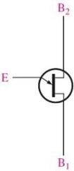 Figure 2
Refer to Figure 2. The symbol is for a
A)a diac
B)a UJT
C)an SCS
D)none of the above
Question
 Figure 5
Refer to Figure 5. The signal you expect to see on the oscilloscope is a
A)sine wave
B)a square wave
C)modified sawtooth wave
D)series of positive trigger pulses
Question
Question
Question
Question
 Figure 4
Refer to Figure 4. The symbol for an SCS is
A)(a)
B)(b)
C)(c)
D)(d)
Question
Question
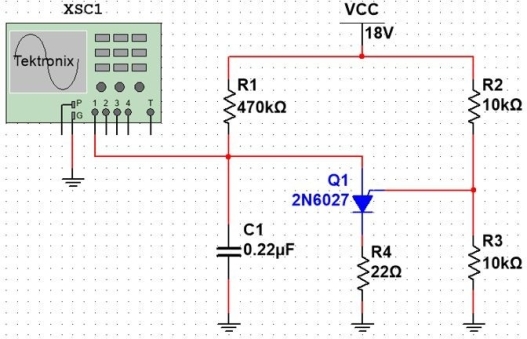 Figure 5
Refer to Figure 5. If the value of R3 is reduced, the output amplitude will _ and the frequency will .
A)decrease, increase
B)decrease, decrease
C)increase, decrease
D)increase, increase
Question
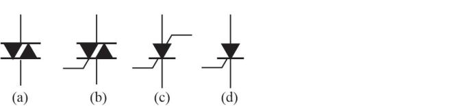 Figure 4
Refer to Figure 4. The symbol for a diac is
A)(a)
B)(b)
C)(c)
D)(d)
Question
 Figure 5
Refer to Figure 5. Q1 is a
A)PUT
B)UJT
C)SCR
D)SCS
Question
Question
Question
Question
Question
Question
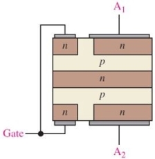 Figure 1
Refer to Figure 1. The type of device that is illustrated by this structure is
A)an SCS
B)a UJT
C)a diac
D)none of the above
Question
Question
Question
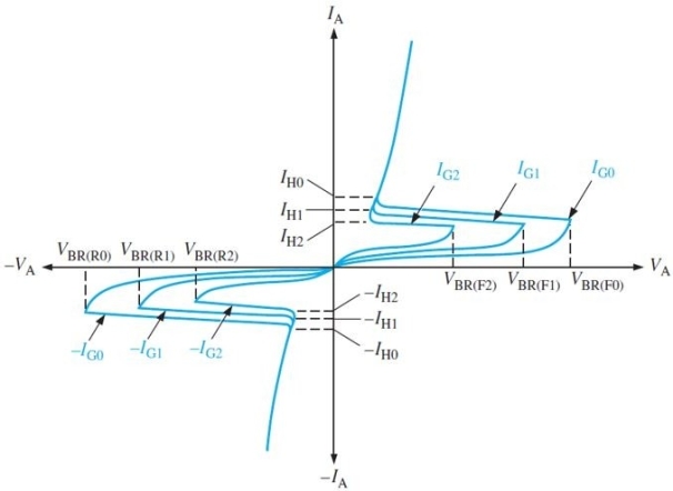 Figure 3
Refer to Figure 3. The characteristic is for
A)a diac
B)a UJT
C)a triac
D)an SCR
Question
Question
Question
Question
Question
Question
Question
Question
Question
Question
Question
Question
Question

Unlock Deck
Sign up to unlock the cards in this deck!
Unlock Deck
Unlock Deck
1/35
Play
Full screen (f)
Deck 11: Thyristors
1
The purpose of an SCR crowbar circuit is to protect a load in case of
A)an open circuit
B)overvoltage
C)power failure
D)all of the above
A)an open circuit
B)overvoltage
C)power failure
D)all of the above
B
2
Assume that a UJT has y = 0.70 when VBB = 10 V. The peak- point emitter voltage is
A)7.0 V
B)7.7 V
C)6.3 V
D)0.7 V
A)7.0 V
B)7.7 V
C)6.3 V
D)0.7 V
B
3
In an SCR, reverse- breakdown voltage VBR(R)is defined at the start of the
A)zener region
B)forward blocking region
C)avalanche region
D)reverse blocking region
A)zener region
B)forward blocking region
C)avalanche region
D)reverse blocking region
C
4
Figure 2Refer to Figure 2. The symbol is for a
A)a diac
B)a UJT
C)an SCS
D)none of the above
Unlock Deck
Unlock for access to all 35 flashcards in this deck.
Unlock Deck
k this deck
5
Figure 5Refer to Figure 5. The signal you expect to see on the oscilloscope is a
A)sine wave
B)a square wave
C)modified sawtooth wave
D)series of positive trigger pulses
Unlock Deck
Unlock for access to all 35 flashcards in this deck.
Unlock Deck
k this deck
6
To stop conduction in an SCR, you could
A)remove gate current
B)apply a negative pulse to the gate
C)both A and B
D)none of the above
A)remove gate current
B)apply a negative pulse to the gate
C)both A and B
D)none of the above
Unlock Deck
Unlock for access to all 35 flashcards in this deck.
Unlock Deck
k this deck
7
The internal base1 resistance for a UJT (r'B1)is controlled by the
A)emitter voltage
B)base2 current
C)emitter current
D)peak point voltage
A)emitter voltage
B)base2 current
C)emitter current
D)peak point voltage
Unlock Deck
Unlock for access to all 35 flashcards in this deck.
Unlock Deck
k this deck
8
The voltage drop across a conducting SCR
A)is half the load voltage
B)is a small negative voltage
C)follows the input voltage
D)is low
A)is half the load voltage
B)is a small negative voltage
C)follows the input voltage
D)is low
Unlock Deck
Unlock for access to all 35 flashcards in this deck.
Unlock Deck
k this deck
9
Figure 4Refer to Figure 4. The symbol for an SCS is
A)(a)
B)(b)
C)(c)
D)(d)
Unlock Deck
Unlock for access to all 35 flashcards in this deck.
Unlock Deck
k this deck
10
A diac is equivalent to two back- to- back inverted
A)triacs
B)four- layer diodes
C)SCRs
D)SCSs
A)triacs
B)four- layer diodes
C)SCRs
D)SCSs
Unlock Deck
Unlock for access to all 35 flashcards in this deck.
Unlock Deck
k this deck
11
Figure 5Refer to Figure 5. If the value of R3 is reduced, the output amplitude will _ and the frequency will .
A)decrease, increase
B)decrease, decrease
C)increase, decrease
D)increase, increase
Unlock Deck
Unlock for access to all 35 flashcards in this deck.
Unlock Deck
k this deck
12
Figure 4Refer to Figure 4. The symbol for a diac is
A)(a)
B)(b)
C)(c)
D)(d)
Unlock Deck
Unlock for access to all 35 flashcards in this deck.
Unlock Deck
k this deck
13
Figure 5Refer to Figure 5. Q1 is a
A)PUT
B)UJT
C)SCR
D)SCS
Unlock Deck
Unlock for access to all 35 flashcards in this deck.
Unlock Deck
k this deck
14
The forward breakover voltage for an SCR
A)is a constant quantity specified by the manufacturer
B)is proportional to VAK
C)is dependent on the maximum specified anode current
D)decreases for increasing IG
A)is a constant quantity specified by the manufacturer
B)is proportional to VAK
C)is dependent on the maximum specified anode current
D)decreases for increasing IG
Unlock Deck
Unlock for access to all 35 flashcards in this deck.
Unlock Deck
k this deck
15
A device that does not have a gate terminal is
A)a triac
B)a diac
C)a LASCR
D)an SCS
A)a triac
B)a diac
C)a LASCR
D)an SCS
Unlock Deck
Unlock for access to all 35 flashcards in this deck.
Unlock Deck
k this deck
16
A device that can be triggered on or off is
A)a triac
B)an SCS
C)both A and B
D)none of the above
A)a triac
B)an SCS
C)both A and B
D)none of the above
Unlock Deck
Unlock for access to all 35 flashcards in this deck.
Unlock Deck
k this deck
17
The number of pn junctions in a UJT is
A)zero
B)one
C)two
D)three
A)zero
B)one
C)two
D)three
Unlock Deck
Unlock for access to all 35 flashcards in this deck.
Unlock Deck
k this deck
18
If a SCR is triggered near 45° of the ac cycle, it will conduct for approximately
A)135°
B)225°
C)315°
D)90°
A)135°
B)225°
C)315°
D)90°
Unlock Deck
Unlock for access to all 35 flashcards in this deck.
Unlock Deck
k this deck
19
Figure 1Refer to Figure 1. The type of device that is illustrated by this structure is
A)an SCS
B)a UJT
C)a diac
D)none of the above
Unlock Deck
Unlock for access to all 35 flashcards in this deck.
Unlock Deck
k this deck
20
A diac will stop conducting if
A)the peak of the applied waveform is reached
B)low- current dropout occurs
C)it receives a negative gate voltage
D)all of the above
A)the peak of the applied waveform is reached
B)low- current dropout occurs
C)it receives a negative gate voltage
D)all of the above
Unlock Deck
Unlock for access to all 35 flashcards in this deck.
Unlock Deck
k this deck
21
A device that can be used to control a dc motor from an ac source is
A)a UJT
B)a diac
C)an SCR
D)none of the above
A)a UJT
B)a diac
C)an SCR
D)none of the above
Unlock Deck
Unlock for access to all 35 flashcards in this deck.
Unlock Deck
k this deck
22
Figure 3Refer to Figure 3. The characteristic is for
A)a diac
B)a UJT
C)a triac
D)an SCR
Unlock Deck
Unlock for access to all 35 flashcards in this deck.
Unlock Deck
k this deck
23
LASCR stands for low- amplitude silicon controlled rectifier.
Unlock Deck
Unlock for access to all 35 flashcards in this deck.
Unlock Deck
k this deck
24
Increasing the firing angle in an SCR control circuit
A)increases the SCR current
B)increases the holding current
C)increases the output current
D)none of the above
A)increases the SCR current
B)increases the holding current
C)increases the output current
D)none of the above
Unlock Deck
Unlock for access to all 35 flashcards in this deck.
Unlock Deck
k this deck
25
An equivalent circuit for a UJT is back- to back npn and pnp transistors.
Unlock Deck
Unlock for access to all 35 flashcards in this deck.
Unlock Deck
k this deck
26
A diac can conduct current in either direction.
Unlock Deck
Unlock for access to all 35 flashcards in this deck.
Unlock Deck
k this deck
27
The characteristic of a UJT that determines its turn- on point is called the
A)blocking point
B)standoff ratio
C)forward breakover voltage
D)trigger current
A)blocking point
B)standoff ratio
C)forward breakover voltage
D)trigger current
Unlock Deck
Unlock for access to all 35 flashcards in this deck.
Unlock Deck
k this deck
28
A device that has a negative resistance region is a
A)a diac
B)an SCS
C)a UJT
D)none of the above
A)a diac
B)an SCS
C)a UJT
D)none of the above
Unlock Deck
Unlock for access to all 35 flashcards in this deck.
Unlock Deck
k this deck
29
A SCR can be turned on
A)by exceeding the forward breakover voltage
B)by forced commutation
C)both A and B
D)none of the above
A)by exceeding the forward breakover voltage
B)by forced commutation
C)both A and B
D)none of the above
Unlock Deck
Unlock for access to all 35 flashcards in this deck.
Unlock Deck
k this deck
30
The conduction angle of an SCR is controlled by the
A)anode voltage
B)timing of gate current pulse
C)load voltage
D)none of the above
A)anode voltage
B)timing of gate current pulse
C)load voltage
D)none of the above
Unlock Deck
Unlock for access to all 35 flashcards in this deck.
Unlock Deck
k this deck
31
An SCR can conduct current in either direction.
Unlock Deck
Unlock for access to all 35 flashcards in this deck.
Unlock Deck
k this deck
32
The gate terminal of a PUT always is biased on.
Unlock Deck
Unlock for access to all 35 flashcards in this deck.
Unlock Deck
k this deck
33
The forward- blocking region of a four- layer diode is from 0 V to VAK = VBR(F).
Unlock Deck
Unlock for access to all 35 flashcards in this deck.
Unlock Deck
k this deck
34
A triac is essentially a bidirectional electronic switch.
Unlock Deck
Unlock for access to all 35 flashcards in this deck.
Unlock Deck
k this deck
35
The IH specification is the highest allowed current in a thyristor.
Unlock Deck
Unlock for access to all 35 flashcards in this deck.
Unlock Deck
k this deck
Unlock Deck
Unlock for access to all 35 flashcards in this deck.


