Deck 4: Common Diode Applications: Clippers, Clampers, Voltage Multipliers, and Displays
Full screen (f)
Question
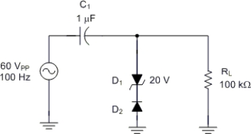
The dc average of the output from the circuit in Figure is approximately equal to
A) +20 V.
B) +10 V.
C) -10 V.
D) -20 V.
Question
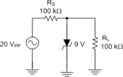
The positive peak output voltage for the circuit in Figure is approximately
A) 9 V.
B) 9.7 V.
C) 8.3 V.
D) 0.7 V.
Question
Assuming that D2 in Figure is an ideal component, the circuit reference voltage is
A) +20 V.
B) +0.7 V.
C) -0.7 V.
D) -20 V.
Question
The circuit in  is a
is a
A) positive clipper.
B) negative clipper.
C) positive clamper.
D) negative clamper.
is aA) positive clipper.
B) negative clipper.
C) positive clamper.
D) negative clamper.
Question
Question
Question
Question
Question

The circuit in Figure is a
A) positive clipper.
B) negative clipper.
C) positive clamper.
D) negative clamper.
Question
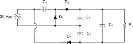
The circuit in Figure is a
A) half-wave voltage doubler.
B) full-wave voltage doubler.
C) voltage tripler.
D) voltage quadrupler.
Question
Question
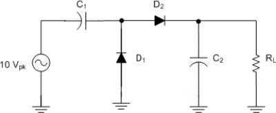
The output from the circuit in is approximately
A) 10.7 Vpp.
B) 5.7 Vpp.
C) 20 Vpp.
D) 9.3 Vpp.
is approximatelyA) 10.7 Vpp.
B) 5.7 Vpp.
C) 20 Vpp.
D) 9.3 Vpp.
Question
The output from the circuit in Figure is approximately
A) 10.7 Vpp.
B) 5.7 Vpp.
C) 20 Vpp.
D) 9.3 Vpp.
Question
Question
The output from the circuit in Figure is approximately
A) 20 Vdc.
B) 30 Vdc.
C) 40 Vdc.
D) 60 Vdc.
Question
Question
The negative peak output voltage for the circuit in Figure is approximately
A) -5 V.
B) -9.7 V.
C) -8.3 V.
D) -0.7 V.
Question
A positive clipper performs the same basic function as a negative clamper.
Question
The circuit in Figure is a
A) series clipper.
B) shunt clipper.
C) series clamper.
D) shunt clamper.
Question
Question
The circuit in Figure is a
A) half-wave voltage doubler.
B) full-wave voltage doubler.
C) voltage tripler.
D) voltage quadrupler.
Question

D2 in Figure will be off when the output from the driving circuit is
A) 0 V.
B) +5 V.
Question
Question

Refer to Figure . The circuit shown has a constant 0-V output. Which of the following is the most likely cause of the problem?
A) RL open
B) D1 open
C) RS open
D) RS shorted
Question
Refer to Figure . The output from the circuit is identical to the input signal. Which of the following is most likely true?
A) The circuit is functioning normally.
B) C1 is open.
C) The load resistor is shorted.
D) The diode is open.
Question
Question
D1 in Figure will be on when the output from the driving circuit is
A) 0 V.
B) +5 V.
Question
Question
Refer to Figure . The potentiometer R1) is used to
A) prevent accidental overload of D1.
B) provide an adjustable clipped output.
C) provide an adjustable clamped output.
D) remove negative voltage spikes.
Question
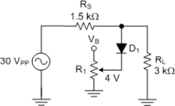
Refer to Figure. The positive peak voltage across the 3 kΩ resistor is
A) 0 V.
B) 0.7 V.
C) 10 V.
D) 4.7 V.
Question
The output voltage from the circuit in Figure is approximately
A) 15 Vdc.
B) 30 Vdc.
C) 45 Vdc.
D) 60 Vdc.
Question
C3 in Figure is included to reduce the ripple in the dc output voltage.
Question

Refer to Figure. Assuming the forward resistance of the diode is 15 Ω, what is the charge time for the capacitor?
A) 10 S
B) 10 mS
C) 75 μS
D) 50 mS

Unlock Deck
Sign up to unlock the cards in this deck!
Unlock Deck
Unlock Deck
1/33
Play
Full screen (f)
Deck 4: Common Diode Applications: Clippers, Clampers, Voltage Multipliers, and Displays
1
The dc average of the output from the circuit in Figure is approximately equal to
A) +20 V.
B) +10 V.
C) -10 V.
D) -20 V.
+10 V.
2
The positive peak output voltage for the circuit in Figure is approximately
A) 9 V.
B) 9.7 V.
C) 8.3 V.
D) 0.7 V.
0.7 V.
3
Assuming that D2 in Figure is an ideal component, the circuit reference voltage is
A) +20 V.
B) +0.7 V.
C) -0.7 V.
D) -20 V.
-20 V.
4
The circuit in is a
A) positive clipper.
B) negative clipper.
C) positive clamper.
D) negative clamper.
is aA) positive clipper.
B) negative clipper.
C) positive clamper.
D) negative clamper.
Unlock Deck
Unlock for access to all 33 flashcards in this deck.
Unlock Deck
k this deck
5
Which of the following determines whether a given clamper is a positive clamper or a negative clamper?
A) The type of diode used
B) The physical orientation of the diode
C) The placement of the diode i.e., in series or shunt with the load)
D) All of the above.
A) The type of diode used
B) The physical orientation of the diode
C) The placement of the diode i.e., in series or shunt with the load)
D) All of the above.
Unlock Deck
Unlock for access to all 33 flashcards in this deck.
Unlock Deck
k this deck
6
Which of the following circuits is used to eliminate some portion of a signal?
A) A clipper
B) A clamper
C) A voltage multiplier
A) A clipper
B) A clamper
C) A voltage multiplier
Unlock Deck
Unlock for access to all 33 flashcards in this deck.
Unlock Deck
k this deck
7
The output from a biased clamper has a dc reference voltage that is
A) approximately equal to the dc voltage that is applied to the diode.
B) approximately equal to 0 V.
C) dependent on the peak-to-peak value of the ac input.
D) equal to the dc average of the circuitʹs output signal.
A) approximately equal to the dc voltage that is applied to the diode.
B) approximately equal to 0 V.
C) dependent on the peak-to-peak value of the ac input.
D) equal to the dc average of the circuitʹs output signal.
Unlock Deck
Unlock for access to all 33 flashcards in this deck.
Unlock Deck
k this deck
8
A clipper is also known as a/an
A) dc restorer.
B) eliminator.
C) limiter.
D) regenerator.
A) dc restorer.
B) eliminator.
C) limiter.
D) regenerator.
Unlock Deck
Unlock for access to all 33 flashcards in this deck.
Unlock Deck
k this deck
9
The circuit in Figure is a
A) positive clipper.
B) negative clipper.
C) positive clamper.
D) negative clamper.
Unlock Deck
Unlock for access to all 33 flashcards in this deck.
Unlock Deck
k this deck
10
The circuit in Figure is a
A) half-wave voltage doubler.
B) full-wave voltage doubler.
C) voltage tripler.
D) voltage quadrupler.
Unlock Deck
Unlock for access to all 33 flashcards in this deck.
Unlock Deck
k this deck
11
Which of the following circuits is used to change the dc reference of a signal without changing its shape?
A) A clipper
B) A clamper
C) A voltage multiplier
A) A clipper
B) A clamper
C) A voltage multiplier
Unlock Deck
Unlock for access to all 33 flashcards in this deck.
Unlock Deck
k this deck
12
The output from the circuit in is approximately
A) 10.7 Vpp.
B) 5.7 Vpp.
C) 20 Vpp.
D) 9.3 Vpp.
is approximatelyA) 10.7 Vpp.
B) 5.7 Vpp.
C) 20 Vpp.
D) 9.3 Vpp.
Unlock Deck
Unlock for access to all 33 flashcards in this deck.
Unlock Deck
k this deck
13
The output from the circuit in Figure is approximately
A) 10.7 Vpp.
B) 5.7 Vpp.
C) 20 Vpp.
D) 9.3 Vpp.
Unlock Deck
Unlock for access to all 33 flashcards in this deck.
Unlock Deck
k this deck
14
The clamper works on the basis of
A) charging alternate capacitors to increase output voltage.
B) shorting out a portion of the input signal to prevent it from reaching the load.
C) switching time constants.
D) alternating dc reference voltages.
A) charging alternate capacitors to increase output voltage.
B) shorting out a portion of the input signal to prevent it from reaching the load.
C) switching time constants.
D) alternating dc reference voltages.
Unlock Deck
Unlock for access to all 33 flashcards in this deck.
Unlock Deck
k this deck
15
The output from the circuit in Figure is approximately
A) 20 Vdc.
B) 30 Vdc.
C) 40 Vdc.
D) 60 Vdc.
Unlock Deck
Unlock for access to all 33 flashcards in this deck.
Unlock Deck
k this deck
16
Which of the following circuits is commonly used to provide transient protection?
A) A clamper
B) A multiplier
C) A rectifier
D) A clipper
A) A clamper
B) A multiplier
C) A rectifier
D) A clipper
Unlock Deck
Unlock for access to all 33 flashcards in this deck.
Unlock Deck
k this deck
17
The negative peak output voltage for the circuit in Figure is approximately
A) -5 V.
B) -9.7 V.
C) -8.3 V.
D) -0.7 V.
Unlock Deck
Unlock for access to all 33 flashcards in this deck.
Unlock Deck
k this deck
18
A positive clipper performs the same basic function as a negative clamper.
Unlock Deck
Unlock for access to all 33 flashcards in this deck.
Unlock Deck
k this deck
19
The circuit in Figure is a
A) series clipper.
B) shunt clipper.
C) series clamper.
D) shunt clamper.
Unlock Deck
Unlock for access to all 33 flashcards in this deck.
Unlock Deck
k this deck
20
A clamper is also known as a/an
A) dc restorer.
B) eliminator.
C) limiter.
D) regenerator.
A) dc restorer.
B) eliminator.
C) limiter.
D) regenerator.
Unlock Deck
Unlock for access to all 33 flashcards in this deck.
Unlock Deck
k this deck
21
The circuit in Figure is a
A) half-wave voltage doubler.
B) full-wave voltage doubler.
C) voltage tripler.
D) voltage quadrupler.
Unlock Deck
Unlock for access to all 33 flashcards in this deck.
Unlock Deck
k this deck
22
D2 in Figure will be off when the output from the driving circuit is
A) 0 V.
B) +5 V.
Unlock Deck
Unlock for access to all 33 flashcards in this deck.
Unlock Deck
k this deck
23
Which of the following is best suited for use in a hand held solar powered low power) calculator?
A) An LED display
B) An LCD display
C) Seven-segment LED display
A) An LED display
B) An LCD display
C) Seven-segment LED display
Unlock Deck
Unlock for access to all 33 flashcards in this deck.
Unlock Deck
k this deck
24
Refer to Figure . The circuit shown has a constant 0-V output. Which of the following is the most likely cause of the problem?
A) RL open
B) D1 open
C) RS open
D) RS shorted
Unlock Deck
Unlock for access to all 33 flashcards in this deck.
Unlock Deck
k this deck
25
Refer to Figure . The output from the circuit is identical to the input signal. Which of the following is most likely true?
A) The circuit is functioning normally.
B) C1 is open.
C) The load resistor is shorted.
D) The diode is open.
Unlock Deck
Unlock for access to all 33 flashcards in this deck.
Unlock Deck
k this deck
26
Which of the following is best suited for use as a computer surge protector?
A) A voltage doubler
B) A clamper
C) A clipper
D) All the above could be used for this purpose.
A) A voltage doubler
B) A clamper
C) A clipper
D) All the above could be used for this purpose.
Unlock Deck
Unlock for access to all 33 flashcards in this deck.
Unlock Deck
k this deck
27
D1 in Figure will be on when the output from the driving circuit is
A) 0 V.
B) +5 V.
Unlock Deck
Unlock for access to all 33 flashcards in this deck.
Unlock Deck
k this deck
28
A display has a single ground pin that is common to all of its LED segments.
A) common-anode
B) common-cathode
C) common-diode
D) common-segment
A) common-anode
B) common-cathode
C) common-diode
D) common-segment
Unlock Deck
Unlock for access to all 33 flashcards in this deck.
Unlock Deck
k this deck
29
Refer to Figure . The potentiometer R1) is used to
A) prevent accidental overload of D1.
B) provide an adjustable clipped output.
C) provide an adjustable clamped output.
D) remove negative voltage spikes.
Unlock Deck
Unlock for access to all 33 flashcards in this deck.
Unlock Deck
k this deck
30
Refer to Figure. The positive peak voltage across the 3 kΩ resistor is
A) 0 V.
B) 0.7 V.
C) 10 V.
D) 4.7 V.
Unlock Deck
Unlock for access to all 33 flashcards in this deck.
Unlock Deck
k this deck
31
The output voltage from the circuit in Figure is approximately
A) 15 Vdc.
B) 30 Vdc.
C) 45 Vdc.
D) 60 Vdc.
Unlock Deck
Unlock for access to all 33 flashcards in this deck.
Unlock Deck
k this deck
32
C3 in Figure is included to reduce the ripple in the dc output voltage.
Unlock Deck
Unlock for access to all 33 flashcards in this deck.
Unlock Deck
k this deck
33
Refer to Figure. Assuming the forward resistance of the diode is 15 Ω, what is the charge time for the capacitor?
A) 10 S
B) 10 mS
C) 75 μS
D) 50 mS
Unlock Deck
Unlock for access to all 33 flashcards in this deck.
Unlock Deck
k this deck
Unlock Deck
Unlock for access to all 33 flashcards in this deck.


