Deck 14: Application of the Laplace Transform to Circuit Analysis
Full screen (f)
Question
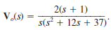
Use Thévenin's theorem to determine v o ( t ) for t 0 in Fig. E14.2.

Figure E14.2
Figure E14.2
Question
Find v o ( t ), t 0, in the network shown in Fig. P14.12 using nodal analysis.
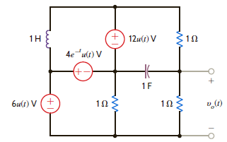
Figure P14.12
Figure P14.12
Question
Use mesh analysis to find v o ( t ) , t 0, in the network in Fig. P14.25.
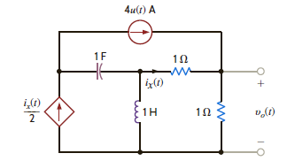
Figure P14.25
Figure P14.25
Question
Use Thévenin's theorem to find v o ( t ), t 0, in the network in Fig. P14.41.
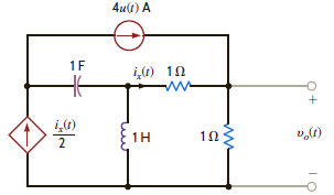
Figure P14.41
Figure P14.41
Question
Find v o ( t ), for t 0, in the network in Fig. P14.57.
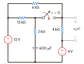
Figure P14.57
Figure P14.57
Question
The voltage response of the network to a unit step input is
 Is the response overdamped
Is the response overdamped Question
Find the steady-state response v o ( t ), t 0, in the network in Fig. P14.89.
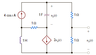
Figure P14.89
Figure P14.89
Question
Assuming that the initial inductor current is zero in the circuit in Fig. 14PFE-5, find the transfer function V o ( s )/ V s ( s ).
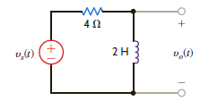
Figure 14PFE-5
a.

b.

c.

d.

Figure 14PFE-5
a.
b.
c.
d.
Question
The transfer function for a network is
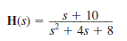
Determine the pole-zero plot of H ( s ), the type of damping exhibited by the network, and the unit step response of the network.
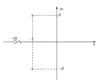
Figure E14.13
Determine the pole-zero plot of H ( s ), the type of damping exhibited by the network, and the unit step response of the network.
Figure E14.13
Question
Use superposition to solve Problem 14.11.
Problem 14.11
Use nodal analysis to find i o ( t ) in the network in Fig. P14.11.

Figure P14.11
Problem 14.11
Use nodal analysis to find i o ( t ) in the network in Fig. P14.11.
Figure P14.11
Question
Use Thévenin's theorem to find v o ( t ), t 0, in the network shown in Fig. P14.42.
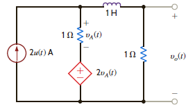
Figure P14.42
Figure P14.42
Question
Find v o ( t ) for t 0 in the network in Fig. P14.58.
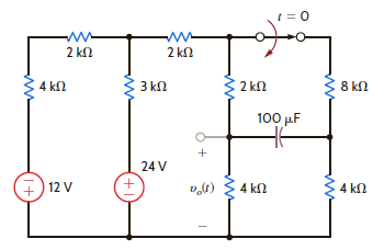
Figure P14.58
Figure P14.58
Question
Find the output voltage, v o ( t ), t 0, in the network in Fig. P14.74a if the input is represented by the waveform shown in Fig. P14.74b.
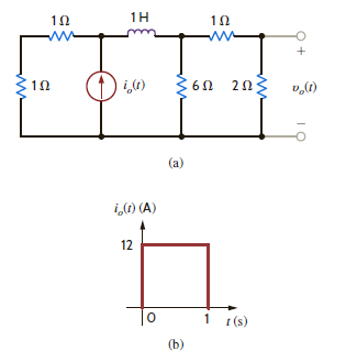
Figure P14.74
Figure P14.74
Question
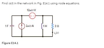
Find v o ( t ), t 0, in the network in Fig. P14.5 using node equations.
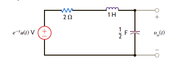
Figure P14.5
Figure P14.5
Question
Find v o ( t ), t 0, in the network in Fig. P14.13.
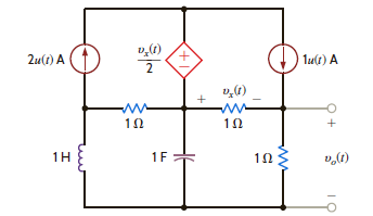
Figure P14.13
Figure P14.13
Question
Use superposition to find v o ( t ) , t 0, in the network shown in Fig. P14.27.
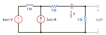
Figure P14.27
Figure P14.27
Question
Use Thévenin's theorem to find i o ( t ), t 0, in the network shown in Fig. P14.43.
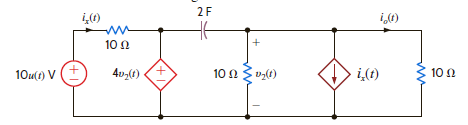
Figure P14.43
Figure P14.43
Question
Find v o ( t ) for t 0 in the network in Fig. P14.59.
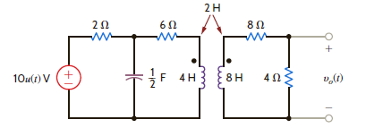
Figure P14.59
Figure P14.59
Question
The voltage response of a network to a unit step input is
 Is the response underdamped
Is the response underdamped Question
Use Thévenin's theorem to determine v o ( t ) for t 0 in Fig. E14.6.
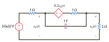
Figure E14.6
Figure E14.6
Question
Determine the steady-state voltage v oss ( t ) in the network in Fig. E14.14 for t 0 if the initial conditions in the network are zero.
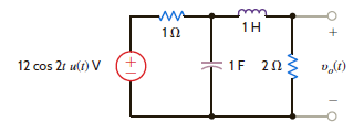
Figure E14.14
Figure E14.14
Question
Use superposition to find v o ( t ), t 0, in the network in Fig. P14.28.
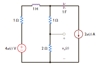
Figure P14.28
Figure P14.28
Question
Find i o ( t ), t 0, in the network shown in Fig. P14.44.
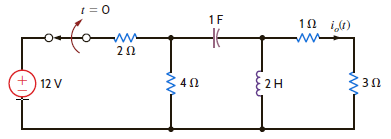
Figure P14.44
Figure P14.44
Question
Find v o ( t ) for t 0 in the network in Fig. P14.60.
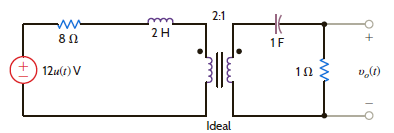
Figure P14.60
Figure P14.60
Question
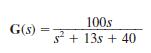
The transfer function of a network is given by the expression
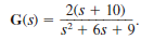 Determine the damping ratio, the undamped natural frequency, and the type of response that will be exhibited by the network.
Determine the damping ratio, the undamped natural frequency, and the type of response that will be exhibited by the network. Question
Question
Use Laplace transforms and nodal analysis to find i 1 ( t ) for t 0 in the network shown in Fig. P14.6. Assume zero initial conditions.
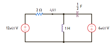
Figure P14.6
Figure P14.6
Question
Use Laplace transforms and mesh analysis to find v o ( t ) for t 0 in the network shown in Fig. P14.14. Assume zero initial conditions.

Figure P14.14
Figure P14.14
Question
Solve Problem 14.14 using Laplace transforms and source transformation.
Problem 14.14
Use Laplace transforms and mesh analysis to find v o ( t ) for t 0 in the network shown in Fig. P14.14. Assume zero initial conditions.

Figure P14.14
Problem 14.14
Use Laplace transforms and mesh analysis to find v o ( t ) for t 0 in the network shown in Fig. P14.14. Assume zero initial conditions.
Figure P14.14
Question
Find i o ( t ), t 0, in the network shown in Fig. P14.45.
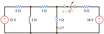
Figure P14.45
Figure P14.45
Question
Determine the initial and final values of the current i ( t ) in the network shown in Fig. P14.61.

Figure P14.61
Figure P14.61
Question
The transfer function of the network is given by the expression
Determine the damping ratio, the undamped natural frequency, and the type of response that will be exhibited by the network.
Determine the damping ratio, the undamped natural frequency, and the type of response that will be exhibited by the network.
Question
A single-loop, second-order circuit is described by the following differential equation:
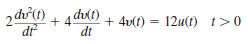
Which is the correct form of the total (natural plus forced) response
a. v ( t ) = K 1 + K 2 e t
b. v ( t ) = K 1 cos t + K 2 sin t
c. v ( t ) = K 1 + K 2 te t
d. v ( t ) = K 1 + K 2 e t cos t + K 3 e t sin t
Which is the correct form of the total (natural plus forced) response
a. v ( t ) = K 1 + K 2 e t
b. v ( t ) = K 1 cos t + K 2 sin t
c. v ( t ) = K 1 + K 2 te t
d. v ( t ) = K 1 + K 2 e t cos t + K 3 e t sin t
Question
Solve Learning Assessment E7.3 on page 261 using Laplace transforms.
Learning Assessment E7.3
In the circuit shown in Fig. E7.3, the switch opens at t = 0. Find i 1 ( t ) for t 0.
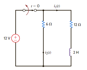
Figure E7.3
Learning Assessment E7.3
In the circuit shown in Fig. E7.3, the switch opens at t = 0. Find i 1 ( t ) for t 0.
Figure E7.3
Question
Find the steady-state response v oss ( t ) in Fig. E14.15.
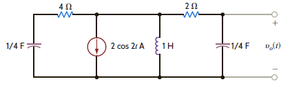
Figure E14.15
Figure E14.15
Question
Use source exchange to solve Problem 14.11.
Problem 14.11
Use nodal analysis to find i o ( t ) in the network in Fig. P14.11.
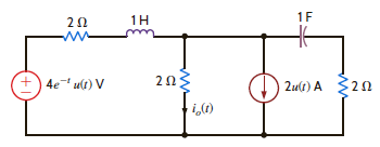
Figure P14.11
Problem 14.11
Use nodal analysis to find i o ( t ) in the network in Fig. P14.11.
Figure P14.11
Question
Find i o ( t ), t 0, in the network in Fig. P14.46.
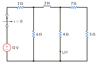
Figure P14.46
Figure P14.46
Question
Determine the initial and final values of the voltage v o ( t ) in the network in Fig. P14.62.
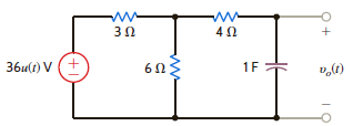
Figure P14.62
Figure P14.62
Question
The voltage response of a network to a unit step input is
Is the response critically damped
Is the response critically damped
Question
Find the input impedance Z ( s ) in the network in Fig. P14.1.
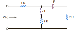
Figure P14.1
Figure P14.1
Question
Use Laplace transforms to find v ( t ) for t 0 in the network shown in Fig. P14.7. Assume zero initial conditions.
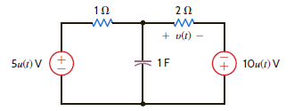
Figure P14.7
Figure P14.7
Question
Solve Problem 14.14 using Laplace transforms and nodal analysis.
Problem 14.14
Use Laplace transforms and mesh analysis to find v o ( t ) for t 0 in the network shown in Fig. P14.14. Assume zero initial conditions.
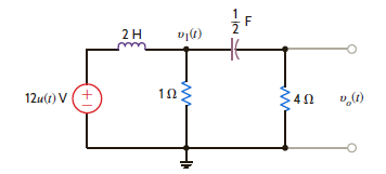
Figure P14.14
Problem 14.14
Use Laplace transforms and mesh analysis to find v o ( t ) for t 0 in the network shown in Fig. P14.14. Assume zero initial conditions.
Figure P14.14
Question
Use source transformation to find v o ( t ), t 0, in the circuit in Fig. P14.31.
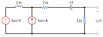
Figure P14.31
Figure P14.31
Question
Find v o ( t ) for t 0 in the network in Fig. P14.47.
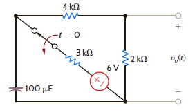
Figure P14.47
Figure P14.47
Question
Find v o ( t ) for t 0 in the network in Fig. P14.63.
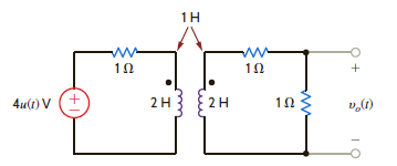
Figure P14.63
Figure P14.63
Question
The transfer function of the network is given by the expression
Determine the damping ratio, the undamped natural frequency, and the type of response that will be exhibited by the network.
Determine the damping ratio, the undamped natural frequency, and the type of response that will be exhibited by the network.
Question
Find v o ( t ) for t 0 in Fig. E14.2 using nodal analysis.
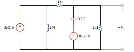
Figure E14.2
Figure E14.2
Question
Solve Learning Assessment E7.6 on page 268 using Laplace transforms.
Learning Assessment E7.6
Consider the network in Fig. E7.6. If the switch opens at t = 0, find the output voltage v o ( t ) for t 0.
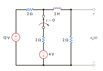
Figure E7.6
Learning Assessment E7.6
Consider the network in Fig. E7.6. If the switch opens at t = 0, find the output voltage v o ( t ) for t 0.
Figure E7.6
Question
Use nodal analysis to find i o ( t ) in the network in Fig. P14.16.

Figure P14.16
Figure P14.16
Question
Solve Problem 14.14 using Laplace transforms and Thévenin's theorem.
Problem 14.14
Use Laplace transforms and mesh analysis to find v o ( t ) for t 0 in the network shown in Fig. P14.14. Assume zero initial conditions.

Figure P14.14
Problem 14.14
Use Laplace transforms and mesh analysis to find v o ( t ) for t 0 in the network shown in Fig. P14.14. Assume zero initial conditions.
Figure P14.14
Question
Find v o ( t ) for t 0 in the network shown in Fig. P14.48.
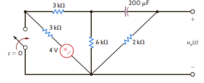
Figure P14.48
Figure P14.48
Question
Find v o ( t ) for t 0 in the network in Fig. P14.64.
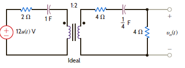
Figure P14.64
Figure P14.64
Question
Find the steady-state response i o ( t ) in the network shown in Fig. P14.80.
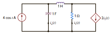
Figure P14.80
Figure P14.80
Question
If all initial conditions are zero in the network in Fig. 14PFE-2, find the transfer function V o ( s )/ V s ( s ).
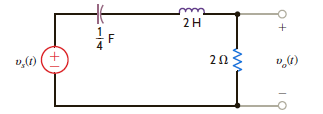
Figure 14PFE-2
a.

b.

c.

d.

Figure 14PFE-2
a.
b.
c.
d.
Question
For the network shown in Fig. P14.8, find v o ( t ), t 0.
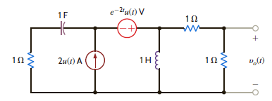
Figure P14.8
Figure P14.8
Question
Use loop equations to find i 1 ( t ) in the network in Fig. P14.17.

Figure P14.17
Figure P14.17
Question
Use Thévenin's theorem to solve Problem 14.16.
Problem 14.16
Use nodal analysis to find i o ( t ) in the network in Fig. P14.16.
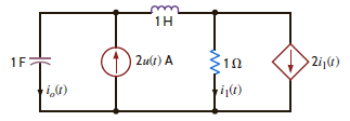
Figure P14.16
Problem 14.16
Use nodal analysis to find i o ( t ) in the network in Fig. P14.16.
Figure P14.16
Question
Find i o ( t ) for t 0 in the network shown in Fig. P14.49.
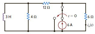
Figure P14.49
Figure P14.49
Question
For the network shown in Fig. P14.65, determine the value of the output voltage as t .
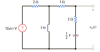
Figure P14.65
Figure P14.65
Question
Find the steady-state response v o ( t ) in the network shown in Fig. P14.81.
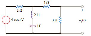
Figure P14.81
Figure P14.81
Question
Find the input impedance Z ( s ) of the network in Fig. P14.2.
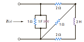
Figure P14.2
Figure P14.2
Question
Find i 0 ( t ) for t 0 in Fig. E14.9.
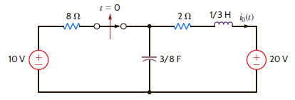
Figure E14.9
Figure E14.9
Question
For the network shown in Fig. P14.18, find v o ( t ), t 0, using mesh equations.
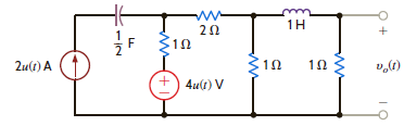
Figure P14.18
Figure P14.18
Question
Use Thévenin's theorem to solve Problem 14.17.
Problem 14.17
Use loop equations to find i 1 ( t ) in the network in Fig. P14.17.
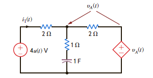
Figure P14.17
Problem 14.17
Use loop equations to find i 1 ( t ) in the network in Fig. P14.17.
Figure P14.17
Question
Find v o ( t ) for t 0 in the network shown in Fig. P14.50.
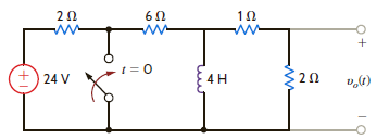
Figure P14.50
Figure P14.50
Question
Determine the initial and final values of the voltage v o ( t ) in the network in Fig. P14.66.
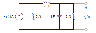
Figure P14.66
Figure P14.66
Question
Find the steady-state response v o ( t ) in the network shown in Fig. P14.82.
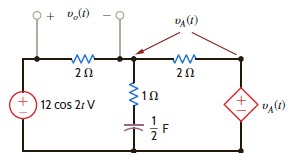
Figure P14.82
Figure P14.82
Question
Find v o ( t ) in the network in Fig. E14.3 using loop equations.
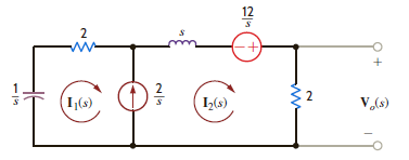
Figure E14.3
Figure E14.3
Question
For the network shown in Fig. P14.9, find i o ( t ), t 0.
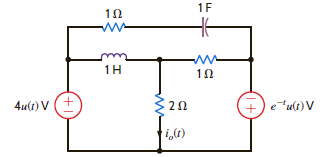
Figure P14.9
Figure P14.9
Question
Use mesh equations to find v o ( t ), t 0, in the network in Fig. P14.19.
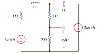
Figure P14.19
Figure P14.19
Question
Use Thévenin's theorem to find i o ( t ), t 0 , in Fig. P14.35.
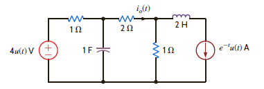
Figure P14.35
Figure P14.35
Question
Find v o ( t ) for t 0 in the network shown in Fig. P14.51.
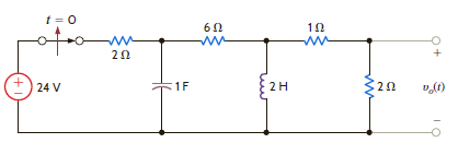
Figure P14.51
Figure P14.51
Question
Given the network in Fig. P14.67, determine the value of the output voltage as t .
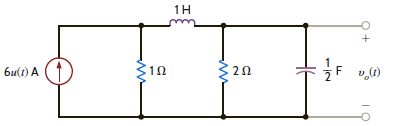
Figure P14.67
Figure P14.67
Question
Determine the steady-state response v o ( t ) for the network in Fig. P14.83.
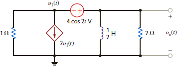
Figure P14.83
Figure P14.83
Question
The initial conditions in the circuit in Fig. 14PFE-3 are zero. Find the transfer function I o ( s )/ I s ( s ).
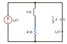
Figure 14PFE-3
a.

b.

c.

d.

Figure 14PFE-3
a.
b.
c.
d.
Question
Find v o ( t ) for t 0 in Fig. E14.10.
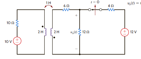
Figure E14.10
Figure E14.10
Question
Use loop analysis to find v o ( t ) for t 0 in the network in Fig. P14.20.
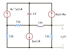
Figure P14.20
Figure P14.20
Question
Use Thévenin's theorem to find v o ( t ), t 0, in the network in Fig. P14.36.
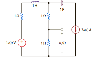
Figure P14.36
Figure P14.36
Question
Find v o ( t ), t 0, in the network shown in Fig. P14.52.
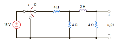
Figure P14.52
Figure P14.52
Question
Determine the output voltage v o ( t ) in the network in Fig. P14.68a if the input is given by the source in Fig. P14.68b.
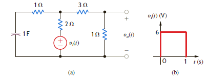
Figure P14.68
Figure P14.68

Unlock Deck
Sign up to unlock the cards in this deck!
Unlock Deck
Unlock Deck
1/109
Play
Full screen (f)
Deck 14: Application of the Laplace Transform to Circuit Analysis
1
Use Thévenin's theorem to determine v o ( t ) for t 0 in Fig. E14.2.
Figure E14.2
Figure E14.2
Refer to Figure E14.2 in the textbook.
The Laplace transformed circuit is,
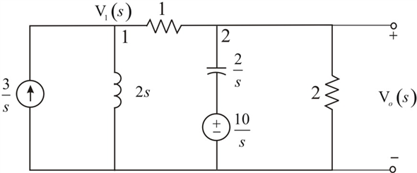 Figure 1
The output voltage is the voltage across the
 resistance.
The Thevenin's equivalent for the circuit can be calculated by removing the
 resistance.
The resulting circuit is,
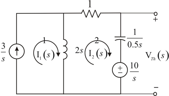 Figure 2
From Figure 2 the current in the first loop is,
 Apply Kirchhoff's Voltage Law to loop 2.

 The Thevenin's equivalent voltage can be calculated as,

 The Thevenin equivalent resistance is calculated by replacing the sources in the network with their internal impedances.
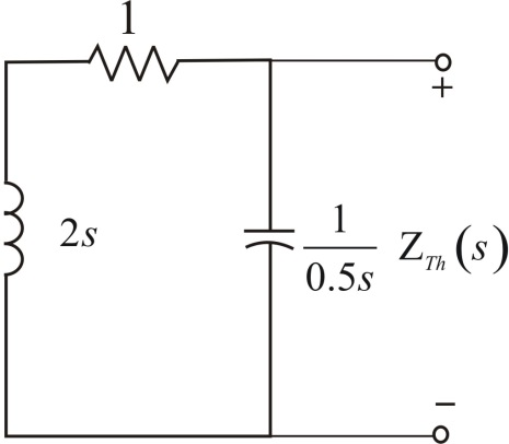 Figure 3
The equivalent impedance is,
 The Thevenin equivalent circuit is,
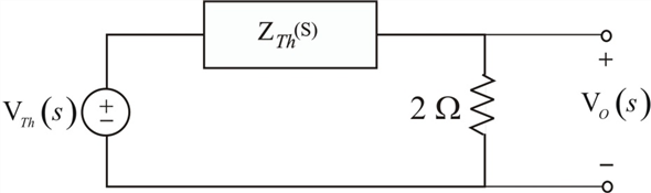 Figure 4
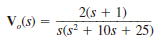
Apply voltage division rule at output.

 Simplify the quadratic equation '
 'we get,

 The equation
 is,
is,
 Express
 in a partial fraction expansion.
 The value of
 is,
is,


 The value of
 is,
is,
 The partial fraction expansion of
 is then
 Apply inverse Laplace transform.
 Thus, the value of the output voltage is,
 .
.
The Laplace transformed circuit is,
Figure 1The output voltage is the voltage across the
resistance.The Thevenin's equivalent for the circuit can be calculated by removing the
resistance.The resulting circuit is,
Figure 2From Figure 2 the current in the first loop is,
Apply Kirchhoff's Voltage Law to loop 2. The Thevenin's equivalent voltage can be calculated as, The Thevenin equivalent resistance is calculated by replacing the sources in the network with their internal impedances. Figure 3The equivalent impedance is,
The Thevenin equivalent circuit is, Figure 4Apply voltage division rule at output.
Simplify the quadratic equation ' 'we get, The equation is, Express in a partial fraction expansion. The value of is, The value of is, The partial fraction expansion of is then Apply inverse Laplace transform. Thus, the value of the output voltage is, . 2
Find v o ( t ), t 0, in the network shown in Fig. P14.12 using nodal analysis.
Figure P14.12
Figure P14.12
Refer to Figure P14.11 in the textbook.
Convert elements into s-domain:

 Draw the circuit diagram in s-domain.
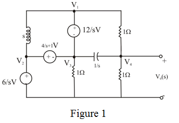 Write the following equations using Figure 1.


 Apply nodal analysis at node
 .
.
 Substitute
 and
and
 expressions.
 Resolve into partial fractions.
 Determine the value of
 .
.
 Determine the value of
 .
.
 Determine the value of
 .
.
 The partial fraction expansion of
 is,
is,
 Apply inverse Laplace transform.
 Therefore, the output voltage is
 .
.
Convert elements into s-domain:
Draw the circuit diagram in s-domain. Write the following equations using Figure 1. Apply nodal analysis at node . Substitute and expressions. Resolve into partial fractions. Determine the value of . Determine the value of . Determine the value of . The partial fraction expansion of is, Apply inverse Laplace transform. Therefore, the output voltage is . 3
Use mesh analysis to find v o ( t ) , t 0, in the network in Fig. P14.25.
Figure P14.25
Figure P14.25
Refer to Figure P14.16 in the textbook.
The Laplace transformed circuit is,
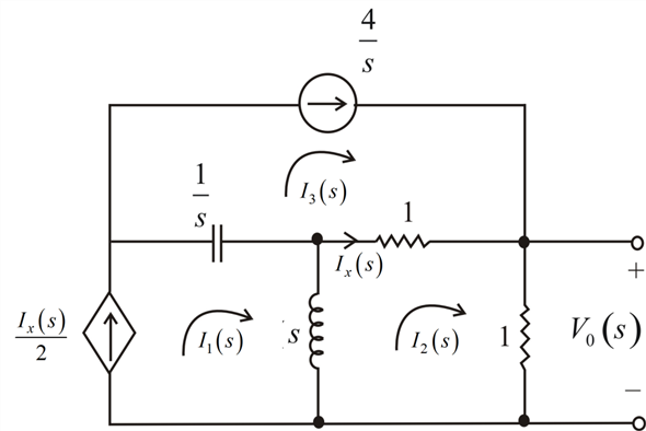 Figure 1
From Figure 1,
 Apply Kirchhoff's Voltage Law to second mesh.

 The output voltage is expressed as,
 Resolve into partial fractions.
 The value of
 is,
is,
 The value of
 is,
is,
 The partial fraction expansion is,
 Apply inverse Laplace transform.
 Therefore, the output voltage is
 .
.
The Laplace transformed circuit is,
Figure 1From Figure 1,
Apply Kirchhoff's Voltage Law to second mesh. The output voltage is expressed as, Resolve into partial fractions. The value of is, The value of is, The partial fraction expansion is, Apply inverse Laplace transform. Therefore, the output voltage is . 4
Use Thévenin's theorem to find v o ( t ), t 0, in the network in Fig. P14.41.
Figure P14.41
Figure P14.41
Unlock Deck
Unlock for access to all 109 flashcards in this deck.
Unlock Deck
k this deck
5
Find v o ( t ), for t 0, in the network in Fig. P14.57.
Figure P14.57
Figure P14.57
Unlock Deck
Unlock for access to all 109 flashcards in this deck.
Unlock Deck
k this deck
6
The voltage response of the network to a unit step input is
Is the response overdamped
Is the response overdamped Unlock Deck
Unlock for access to all 109 flashcards in this deck.
Unlock Deck
k this deck
7
Find the steady-state response v o ( t ), t 0, in the network in Fig. P14.89.
Figure P14.89
Figure P14.89
Unlock Deck
Unlock for access to all 109 flashcards in this deck.
Unlock Deck
k this deck
8
Assuming that the initial inductor current is zero in the circuit in Fig. 14PFE-5, find the transfer function V o ( s )/ V s ( s ).
Figure 14PFE-5
a.
b.
c.
d.
Figure 14PFE-5
a.
b.
c.
d.
Unlock Deck
Unlock for access to all 109 flashcards in this deck.
Unlock Deck
k this deck
9
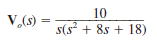
The transfer function for a network is
Determine the pole-zero plot of H ( s ), the type of damping exhibited by the network, and the unit step response of the network.
Figure E14.13
Determine the pole-zero plot of H ( s ), the type of damping exhibited by the network, and the unit step response of the network.
Figure E14.13
Unlock Deck
Unlock for access to all 109 flashcards in this deck.
Unlock Deck
k this deck
10
Use superposition to solve Problem 14.11.
Problem 14.11
Use nodal analysis to find i o ( t ) in the network in Fig. P14.11.
Figure P14.11
Problem 14.11
Use nodal analysis to find i o ( t ) in the network in Fig. P14.11.
Figure P14.11
Unlock Deck
Unlock for access to all 109 flashcards in this deck.
Unlock Deck
k this deck
11
Use Thévenin's theorem to find v o ( t ), t 0, in the network shown in Fig. P14.42.
Figure P14.42
Figure P14.42
Unlock Deck
Unlock for access to all 109 flashcards in this deck.
Unlock Deck
k this deck
12
Find v o ( t ) for t 0 in the network in Fig. P14.58.
Figure P14.58
Figure P14.58
Unlock Deck
Unlock for access to all 109 flashcards in this deck.
Unlock Deck
k this deck
13
Find the output voltage, v o ( t ), t 0, in the network in Fig. P14.74a if the input is represented by the waveform shown in Fig. P14.74b.
Figure P14.74
Figure P14.74
Unlock Deck
Unlock for access to all 109 flashcards in this deck.
Unlock Deck
k this deck
14
Find v o ( t ), t 0, in the network in Fig. P14.5 using node equations.
Figure P14.5
Figure P14.5
Unlock Deck
Unlock for access to all 109 flashcards in this deck.
Unlock Deck
k this deck
15
Find v o ( t ), t 0, in the network in Fig. P14.13.
Figure P14.13
Figure P14.13
Unlock Deck
Unlock for access to all 109 flashcards in this deck.
Unlock Deck
k this deck
16
Use superposition to find v o ( t ) , t 0, in the network shown in Fig. P14.27.
Figure P14.27
Figure P14.27
Unlock Deck
Unlock for access to all 109 flashcards in this deck.
Unlock Deck
k this deck
17
Use Thévenin's theorem to find i o ( t ), t 0, in the network shown in Fig. P14.43.
Figure P14.43
Figure P14.43
Unlock Deck
Unlock for access to all 109 flashcards in this deck.
Unlock Deck
k this deck
18
Find v o ( t ) for t 0 in the network in Fig. P14.59.
Figure P14.59
Figure P14.59
Unlock Deck
Unlock for access to all 109 flashcards in this deck.
Unlock Deck
k this deck
19
The voltage response of a network to a unit step input is
Is the response underdamped
Is the response underdamped Unlock Deck
Unlock for access to all 109 flashcards in this deck.
Unlock Deck
k this deck
20
Use Thévenin's theorem to determine v o ( t ) for t 0 in Fig. E14.6.
Figure E14.6
Figure E14.6
Unlock Deck
Unlock for access to all 109 flashcards in this deck.
Unlock Deck
k this deck
21
Determine the steady-state voltage v oss ( t ) in the network in Fig. E14.14 for t 0 if the initial conditions in the network are zero.
Figure E14.14
Figure E14.14
Unlock Deck
Unlock for access to all 109 flashcards in this deck.
Unlock Deck
k this deck
22
Use superposition to find v o ( t ), t 0, in the network in Fig. P14.28.
Figure P14.28
Figure P14.28
Unlock Deck
Unlock for access to all 109 flashcards in this deck.
Unlock Deck
k this deck
23
Find i o ( t ), t 0, in the network shown in Fig. P14.44.
Figure P14.44
Figure P14.44
Unlock Deck
Unlock for access to all 109 flashcards in this deck.
Unlock Deck
k this deck
24
Find v o ( t ) for t 0 in the network in Fig. P14.60.
Figure P14.60
Figure P14.60
Unlock Deck
Unlock for access to all 109 flashcards in this deck.
Unlock Deck
k this deck
25
The transfer function of a network is given by the expression
Determine the damping ratio, the undamped natural frequency, and the type of response that will be exhibited by the network.
Determine the damping ratio, the undamped natural frequency, and the type of response that will be exhibited by the network. Unlock Deck
Unlock for access to all 109 flashcards in this deck.
Unlock Deck
k this deck
26
Unlock Deck
Unlock for access to all 109 flashcards in this deck.
Unlock Deck
k this deck
27
Use Laplace transforms and nodal analysis to find i 1 ( t ) for t 0 in the network shown in Fig. P14.6. Assume zero initial conditions.
Figure P14.6
Figure P14.6
Unlock Deck
Unlock for access to all 109 flashcards in this deck.
Unlock Deck
k this deck
28
Use Laplace transforms and mesh analysis to find v o ( t ) for t 0 in the network shown in Fig. P14.14. Assume zero initial conditions.
Figure P14.14
Figure P14.14
Unlock Deck
Unlock for access to all 109 flashcards in this deck.
Unlock Deck
k this deck
29
Solve Problem 14.14 using Laplace transforms and source transformation.
Problem 14.14
Use Laplace transforms and mesh analysis to find v o ( t ) for t 0 in the network shown in Fig. P14.14. Assume zero initial conditions.
Figure P14.14
Problem 14.14
Use Laplace transforms and mesh analysis to find v o ( t ) for t 0 in the network shown in Fig. P14.14. Assume zero initial conditions.
Figure P14.14
Unlock Deck
Unlock for access to all 109 flashcards in this deck.
Unlock Deck
k this deck
30
Find i o ( t ), t 0, in the network shown in Fig. P14.45.
Figure P14.45
Figure P14.45
Unlock Deck
Unlock for access to all 109 flashcards in this deck.
Unlock Deck
k this deck
31
Determine the initial and final values of the current i ( t ) in the network shown in Fig. P14.61.
Figure P14.61
Figure P14.61
Unlock Deck
Unlock for access to all 109 flashcards in this deck.
Unlock Deck
k this deck
32
The transfer function of the network is given by the expression
Determine the damping ratio, the undamped natural frequency, and the type of response that will be exhibited by the network.
Determine the damping ratio, the undamped natural frequency, and the type of response that will be exhibited by the network.
Unlock Deck
Unlock for access to all 109 flashcards in this deck.
Unlock Deck
k this deck
33
A single-loop, second-order circuit is described by the following differential equation:
Which is the correct form of the total (natural plus forced) response
a. v ( t ) = K 1 + K 2 e t
b. v ( t ) = K 1 cos t + K 2 sin t
c. v ( t ) = K 1 + K 2 te t
d. v ( t ) = K 1 + K 2 e t cos t + K 3 e t sin t
Which is the correct form of the total (natural plus forced) response
a. v ( t ) = K 1 + K 2 e t
b. v ( t ) = K 1 cos t + K 2 sin t
c. v ( t ) = K 1 + K 2 te t
d. v ( t ) = K 1 + K 2 e t cos t + K 3 e t sin t
Unlock Deck
Unlock for access to all 109 flashcards in this deck.
Unlock Deck
k this deck
34
Solve Learning Assessment E7.3 on page 261 using Laplace transforms.
Learning Assessment E7.3
In the circuit shown in Fig. E7.3, the switch opens at t = 0. Find i 1 ( t ) for t 0.
Figure E7.3
Learning Assessment E7.3
In the circuit shown in Fig. E7.3, the switch opens at t = 0. Find i 1 ( t ) for t 0.
Figure E7.3
Unlock Deck
Unlock for access to all 109 flashcards in this deck.
Unlock Deck
k this deck
35
Find the steady-state response v oss ( t ) in Fig. E14.15.
Figure E14.15
Figure E14.15
Unlock Deck
Unlock for access to all 109 flashcards in this deck.
Unlock Deck
k this deck
36
Use source exchange to solve Problem 14.11.
Problem 14.11
Use nodal analysis to find i o ( t ) in the network in Fig. P14.11.
Figure P14.11
Problem 14.11
Use nodal analysis to find i o ( t ) in the network in Fig. P14.11.
Figure P14.11
Unlock Deck
Unlock for access to all 109 flashcards in this deck.
Unlock Deck
k this deck
37
Find i o ( t ), t 0, in the network in Fig. P14.46.
Figure P14.46
Figure P14.46
Unlock Deck
Unlock for access to all 109 flashcards in this deck.
Unlock Deck
k this deck
38
Determine the initial and final values of the voltage v o ( t ) in the network in Fig. P14.62.
Figure P14.62
Figure P14.62
Unlock Deck
Unlock for access to all 109 flashcards in this deck.
Unlock Deck
k this deck
39
The voltage response of a network to a unit step input is
Is the response critically damped
Is the response critically damped
Unlock Deck
Unlock for access to all 109 flashcards in this deck.
Unlock Deck
k this deck
40
Find the input impedance Z ( s ) in the network in Fig. P14.1.
Figure P14.1
Figure P14.1
Unlock Deck
Unlock for access to all 109 flashcards in this deck.
Unlock Deck
k this deck
41
Use Laplace transforms to find v ( t ) for t 0 in the network shown in Fig. P14.7. Assume zero initial conditions.
Figure P14.7
Figure P14.7
Unlock Deck
Unlock for access to all 109 flashcards in this deck.
Unlock Deck
k this deck
42
Solve Problem 14.14 using Laplace transforms and nodal analysis.
Problem 14.14
Use Laplace transforms and mesh analysis to find v o ( t ) for t 0 in the network shown in Fig. P14.14. Assume zero initial conditions.
Figure P14.14
Problem 14.14
Use Laplace transforms and mesh analysis to find v o ( t ) for t 0 in the network shown in Fig. P14.14. Assume zero initial conditions.
Figure P14.14
Unlock Deck
Unlock for access to all 109 flashcards in this deck.
Unlock Deck
k this deck
43
Use source transformation to find v o ( t ), t 0, in the circuit in Fig. P14.31.
Figure P14.31
Figure P14.31
Unlock Deck
Unlock for access to all 109 flashcards in this deck.
Unlock Deck
k this deck
44
Find v o ( t ) for t 0 in the network in Fig. P14.47.
Figure P14.47
Figure P14.47
Unlock Deck
Unlock for access to all 109 flashcards in this deck.
Unlock Deck
k this deck
45
Find v o ( t ) for t 0 in the network in Fig. P14.63.
Figure P14.63
Figure P14.63
Unlock Deck
Unlock for access to all 109 flashcards in this deck.
Unlock Deck
k this deck
46
The transfer function of the network is given by the expression
Determine the damping ratio, the undamped natural frequency, and the type of response that will be exhibited by the network.
Determine the damping ratio, the undamped natural frequency, and the type of response that will be exhibited by the network.
Unlock Deck
Unlock for access to all 109 flashcards in this deck.
Unlock Deck
k this deck
47
Find v o ( t ) for t 0 in Fig. E14.2 using nodal analysis.
Figure E14.2
Figure E14.2
Unlock Deck
Unlock for access to all 109 flashcards in this deck.
Unlock Deck
k this deck
48
Solve Learning Assessment E7.6 on page 268 using Laplace transforms.
Learning Assessment E7.6
Consider the network in Fig. E7.6. If the switch opens at t = 0, find the output voltage v o ( t ) for t 0.
Figure E7.6
Learning Assessment E7.6
Consider the network in Fig. E7.6. If the switch opens at t = 0, find the output voltage v o ( t ) for t 0.
Figure E7.6
Unlock Deck
Unlock for access to all 109 flashcards in this deck.
Unlock Deck
k this deck
49
Use nodal analysis to find i o ( t ) in the network in Fig. P14.16.
Figure P14.16
Figure P14.16
Unlock Deck
Unlock for access to all 109 flashcards in this deck.
Unlock Deck
k this deck
50
Solve Problem 14.14 using Laplace transforms and Thévenin's theorem.
Problem 14.14
Use Laplace transforms and mesh analysis to find v o ( t ) for t 0 in the network shown in Fig. P14.14. Assume zero initial conditions.
Figure P14.14
Problem 14.14
Use Laplace transforms and mesh analysis to find v o ( t ) for t 0 in the network shown in Fig. P14.14. Assume zero initial conditions.
Figure P14.14
Unlock Deck
Unlock for access to all 109 flashcards in this deck.
Unlock Deck
k this deck
51
Find v o ( t ) for t 0 in the network shown in Fig. P14.48.
Figure P14.48
Figure P14.48
Unlock Deck
Unlock for access to all 109 flashcards in this deck.
Unlock Deck
k this deck
52
Find v o ( t ) for t 0 in the network in Fig. P14.64.
Figure P14.64
Figure P14.64
Unlock Deck
Unlock for access to all 109 flashcards in this deck.
Unlock Deck
k this deck
53
Find the steady-state response i o ( t ) in the network shown in Fig. P14.80.
Figure P14.80
Figure P14.80
Unlock Deck
Unlock for access to all 109 flashcards in this deck.
Unlock Deck
k this deck
54
If all initial conditions are zero in the network in Fig. 14PFE-2, find the transfer function V o ( s )/ V s ( s ).
Figure 14PFE-2
a.
b.
c.
d.
Figure 14PFE-2
a.
b.
c.
d.
Unlock Deck
Unlock for access to all 109 flashcards in this deck.
Unlock Deck
k this deck
55
For the network shown in Fig. P14.8, find v o ( t ), t 0.
Figure P14.8
Figure P14.8
Unlock Deck
Unlock for access to all 109 flashcards in this deck.
Unlock Deck
k this deck
56
Use loop equations to find i 1 ( t ) in the network in Fig. P14.17.
Figure P14.17
Figure P14.17
Unlock Deck
Unlock for access to all 109 flashcards in this deck.
Unlock Deck
k this deck
57
Use Thévenin's theorem to solve Problem 14.16.
Problem 14.16
Use nodal analysis to find i o ( t ) in the network in Fig. P14.16.
Figure P14.16
Problem 14.16
Use nodal analysis to find i o ( t ) in the network in Fig. P14.16.
Figure P14.16
Unlock Deck
Unlock for access to all 109 flashcards in this deck.
Unlock Deck
k this deck
58
Find i o ( t ) for t 0 in the network shown in Fig. P14.49.
Figure P14.49
Figure P14.49
Unlock Deck
Unlock for access to all 109 flashcards in this deck.
Unlock Deck
k this deck
59
For the network shown in Fig. P14.65, determine the value of the output voltage as t .
Figure P14.65
Figure P14.65
Unlock Deck
Unlock for access to all 109 flashcards in this deck.
Unlock Deck
k this deck
60
Find the steady-state response v o ( t ) in the network shown in Fig. P14.81.
Figure P14.81
Figure P14.81
Unlock Deck
Unlock for access to all 109 flashcards in this deck.
Unlock Deck
k this deck
61
Find the input impedance Z ( s ) of the network in Fig. P14.2.
Figure P14.2
Figure P14.2
Unlock Deck
Unlock for access to all 109 flashcards in this deck.
Unlock Deck
k this deck
62
Find i 0 ( t ) for t 0 in Fig. E14.9.
Figure E14.9
Figure E14.9
Unlock Deck
Unlock for access to all 109 flashcards in this deck.
Unlock Deck
k this deck
63
For the network shown in Fig. P14.18, find v o ( t ), t 0, using mesh equations.
Figure P14.18
Figure P14.18
Unlock Deck
Unlock for access to all 109 flashcards in this deck.
Unlock Deck
k this deck
64
Use Thévenin's theorem to solve Problem 14.17.
Problem 14.17
Use loop equations to find i 1 ( t ) in the network in Fig. P14.17.
Figure P14.17
Problem 14.17
Use loop equations to find i 1 ( t ) in the network in Fig. P14.17.
Figure P14.17
Unlock Deck
Unlock for access to all 109 flashcards in this deck.
Unlock Deck
k this deck
65
Find v o ( t ) for t 0 in the network shown in Fig. P14.50.
Figure P14.50
Figure P14.50
Unlock Deck
Unlock for access to all 109 flashcards in this deck.
Unlock Deck
k this deck
66
Determine the initial and final values of the voltage v o ( t ) in the network in Fig. P14.66.
Figure P14.66
Figure P14.66
Unlock Deck
Unlock for access to all 109 flashcards in this deck.
Unlock Deck
k this deck
67
Find the steady-state response v o ( t ) in the network shown in Fig. P14.82.
Figure P14.82
Figure P14.82
Unlock Deck
Unlock for access to all 109 flashcards in this deck.
Unlock Deck
k this deck
68
Find v o ( t ) in the network in Fig. E14.3 using loop equations.
Figure E14.3
Figure E14.3
Unlock Deck
Unlock for access to all 109 flashcards in this deck.
Unlock Deck
k this deck
69
For the network shown in Fig. P14.9, find i o ( t ), t 0.
Figure P14.9
Figure P14.9
Unlock Deck
Unlock for access to all 109 flashcards in this deck.
Unlock Deck
k this deck
70
Use mesh equations to find v o ( t ), t 0, in the network in Fig. P14.19.
Figure P14.19
Figure P14.19
Unlock Deck
Unlock for access to all 109 flashcards in this deck.
Unlock Deck
k this deck
71
Use Thévenin's theorem to find i o ( t ), t 0 , in Fig. P14.35.
Figure P14.35
Figure P14.35
Unlock Deck
Unlock for access to all 109 flashcards in this deck.
Unlock Deck
k this deck
72
Find v o ( t ) for t 0 in the network shown in Fig. P14.51.
Figure P14.51
Figure P14.51
Unlock Deck
Unlock for access to all 109 flashcards in this deck.
Unlock Deck
k this deck
73
Given the network in Fig. P14.67, determine the value of the output voltage as t .
Figure P14.67
Figure P14.67
Unlock Deck
Unlock for access to all 109 flashcards in this deck.
Unlock Deck
k this deck
74
Determine the steady-state response v o ( t ) for the network in Fig. P14.83.
Figure P14.83
Figure P14.83
Unlock Deck
Unlock for access to all 109 flashcards in this deck.
Unlock Deck
k this deck
75
The initial conditions in the circuit in Fig. 14PFE-3 are zero. Find the transfer function I o ( s )/ I s ( s ).
Figure 14PFE-3
a.
b.
c.
d.
Figure 14PFE-3
a.
b.
c.
d.
Unlock Deck
Unlock for access to all 109 flashcards in this deck.
Unlock Deck
k this deck
76
Find v o ( t ) for t 0 in Fig. E14.10.
Figure E14.10
Figure E14.10
Unlock Deck
Unlock for access to all 109 flashcards in this deck.
Unlock Deck
k this deck
77
Use loop analysis to find v o ( t ) for t 0 in the network in Fig. P14.20.
Figure P14.20
Figure P14.20
Unlock Deck
Unlock for access to all 109 flashcards in this deck.
Unlock Deck
k this deck
78
Use Thévenin's theorem to find v o ( t ), t 0, in the network in Fig. P14.36.
Figure P14.36
Figure P14.36
Unlock Deck
Unlock for access to all 109 flashcards in this deck.
Unlock Deck
k this deck
79
Find v o ( t ), t 0, in the network shown in Fig. P14.52.
Figure P14.52
Figure P14.52
Unlock Deck
Unlock for access to all 109 flashcards in this deck.
Unlock Deck
k this deck
80
Determine the output voltage v o ( t ) in the network in Fig. P14.68a if the input is given by the source in Fig. P14.68b.
Figure P14.68
Figure P14.68
Unlock Deck
Unlock for access to all 109 flashcards in this deck.
Unlock Deck
k this deck
Unlock Deck
Unlock for access to all 109 flashcards in this deck.


