Deck 10: Electromagnetism
Full screen (f)
Question
Question
Question
Question
Question
Question
Question
Question
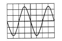
A sinusoidal voltage trace displayed on an oscilloscope is shown in Figure RT3.1; the 'time/cm' switch is on 50 ms and the 'volts/cm' switch is on 2 V/cm. Determine for the waveform
(a) the frequency (b) the peak-to-peak voltage (c) the amplitude (d) the r.m.s. value.
Figure RT3.1
(a) the frequency (b) the peak-to-peak voltage (c) the amplitude (d) the r.m.s. value.
Figure RT3.1
Question
Question
Question
The following values were obtained during an experiment on a varactor diode.
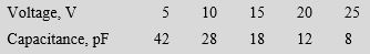 Plot a graph showing the variation of capacitance with voltage for the varactor. Label your axes clearly
and use your graph to determine (a) the capacitance when the reverse voltage is - 17.5 V, (b) the
reverse voltage for a capacitance of 35 pF, and (c) the change in capacitance when the voltage changes
from −2.5 V to −22.5 V
Plot a graph showing the variation of capacitance with voltage for the varactor. Label your axes clearlyand use your graph to determine (a) the capacitance when the reverse voltage is - 17.5 V, (b) the
reverse voltage for a capacitance of 35 pF, and (c) the change in capacitance when the voltage changes
from −2.5 V to −22.5 V
Question
Question
The output characteristics of a common-emitter transistor amplifier are given below. Assume that the characteristics are linear between the values of collector voltage stated.
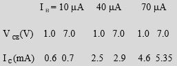 Plot the characteristics and superimpose the load line for a 1.5 k load resistor and collector supply voltage of 8 V. The signal input resistance is 1.2 k. When a peak input current of 30 A varies sinusoidally about a mean bias of 40 A, determine (a) the quiescent values of collector voltage and current, (b) the output voltage swing, (c) the voltage gain, (d) the dynamic current gain, and (e) the power gain.
Plot the characteristics and superimpose the load line for a 1.5 k load resistor and collector supply voltage of 8 V. The signal input resistance is 1.2 k. When a peak input current of 30 A varies sinusoidally about a mean bias of 40 A, determine (a) the quiescent values of collector voltage and current, (b) the output voltage swing, (c) the voltage gain, (d) the dynamic current gain, and (e) the power gain.
Unlock Deck
Sign up to unlock the cards in this deck!
Unlock Deck
Unlock Deck
1/13
Play
Full screen (f)
Deck 10: Electromagnetism
1
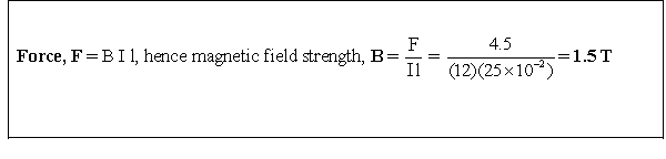
A conductor, 25 cm long is situated at right angles to a magnetic field. Determine the strength of the magnetic field if a current of 12 A in the conductor produces a force on it of 4.5 N
2
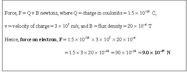
An electron in a television tube has a charge of 1.5 10-19C and travels at 3 107m/s perpendicular to a field of flux density 20 T. Calculate the force exerted on the electron in the field.
3
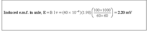
A lorry is travelling at 100 km/h. Assuming the vertical component of the earth's magnetic field is 40 T and the back axle of the lorry is 1.98 m, find the e.m.f. generated in the axle due to motion.
4
An e.m.f. of 2.5 kV is induced in a coil when a current of 2 A collapses to zero in 5 ms. Calculate the inductance of the coil.
Unlock Deck
Unlock for access to all 13 flashcards in this deck.
Unlock Deck
k this deck
5
Two coils, P and Q, have a mutual inductance of 100 mH. If a current of 3 A in coil P is reversed in 20 ms, determine (a) the average e.m.f. induced in coil Q, and (b) the flux change linked with coil Q if it is wound with 200 turns.
Unlock Deck
Unlock for access to all 13 flashcards in this deck.
Unlock Deck
k this deck
6
A moving coil instrument gives a f.s.d. when the current is 50 mA and has a resistance of 40 . Determine the value of resistance required to enable the instrument to be used (a) as a 0-5 A ammeter, and (b) as a 0-200 V voltmeter. State the mode of connection in each case.
Unlock Deck
Unlock for access to all 13 flashcards in this deck.
Unlock Deck
k this deck
7
An amplifier has a gain of 20 dB. It's input power is 5 mW. Calculate it's output power.
Unlock Deck
Unlock for access to all 13 flashcards in this deck.
Unlock Deck
k this deck
8
A sinusoidal voltage trace displayed on an oscilloscope is shown in Figure RT3.1; the 'time/cm' switch is on 50 ms and the 'volts/cm' switch is on 2 V/cm. Determine for the waveform
(a) the frequency (b) the peak-to-peak voltage (c) the amplitude (d) the r.m.s. value.
Figure RT3.1
(a) the frequency (b) the peak-to-peak voltage (c) the amplitude (d) the r.m.s. value.
Figure RT3.1
Unlock Deck
Unlock for access to all 13 flashcards in this deck.
Unlock Deck
k this deck
9
With reference to a p-n junction, briefly explain the terms: (a) majority carriers (b) contact potential (c) depletion layer (d) forward bias (e) reverse bias.
Unlock Deck
Unlock for access to all 13 flashcards in this deck.
Unlock Deck
k this deck
10
Briefly describe each of the following, drawing their circuit diagram symbol and stating
typical applications: (a) zenor diode (b) silicon controlled rectifier (c) light emitting diode
(d) varactor diode (e) Schottky diode
typical applications: (a) zenor diode (b) silicon controlled rectifier (c) light emitting diode
(d) varactor diode (e) Schottky diode
Unlock Deck
Unlock for access to all 13 flashcards in this deck.
Unlock Deck
k this deck
11
The following values were obtained during an experiment on a varactor diode.
Plot a graph showing the variation of capacitance with voltage for the varactor. Label your axes clearly
and use your graph to determine (a) the capacitance when the reverse voltage is - 17.5 V, (b) the
reverse voltage for a capacitance of 35 pF, and (c) the change in capacitance when the voltage changes
from −2.5 V to −22.5 V
Plot a graph showing the variation of capacitance with voltage for the varactor. Label your axes clearlyand use your graph to determine (a) the capacitance when the reverse voltage is - 17.5 V, (b) the
reverse voltage for a capacitance of 35 pF, and (c) the change in capacitance when the voltage changes
from −2.5 V to −22.5 V
Unlock Deck
Unlock for access to all 13 flashcards in this deck.
Unlock Deck
k this deck
12
Briefly describe, with diagrams, the action of an n-p-n transistor.
Unlock Deck
Unlock for access to all 13 flashcards in this deck.
Unlock Deck
k this deck
13
The output characteristics of a common-emitter transistor amplifier are given below. Assume that the characteristics are linear between the values of collector voltage stated.
Plot the characteristics and superimpose the load line for a 1.5 k load resistor and collector supply voltage of 8 V. The signal input resistance is 1.2 k. When a peak input current of 30 A varies sinusoidally about a mean bias of 40 A, determine (a) the quiescent values of collector voltage and current, (b) the output voltage swing, (c) the voltage gain, (d) the dynamic current gain, and (e) the power gain.
Plot the characteristics and superimpose the load line for a 1.5 k load resistor and collector supply voltage of 8 V. The signal input resistance is 1.2 k. When a peak input current of 30 A varies sinusoidally about a mean bias of 40 A, determine (a) the quiescent values of collector voltage and current, (b) the output voltage swing, (c) the voltage gain, (d) the dynamic current gain, and (e) the power gain. Unlock Deck
Unlock for access to all 13 flashcards in this deck.
Unlock Deck
k this deck
Unlock Deck
Unlock for access to all 13 flashcards in this deck.


