Deck 9: Counters
Full screen (f)
Question
Question
Question
Question
Question
Question
Question
Question
Question
Question
Question
Question
Question
Question
Question
Question
? 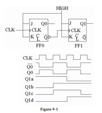
-The counter shown in Figure 9- 1 is a(n) __________ counter, and the correct output waveform for Q1 is__________ .
A) synchronous, Q1a
B) asynchronous, Q1b
C) asynchronous, Q1c
D) synchronous, Q1d
-The counter shown in Figure 9- 1 is a(n) __________ counter, and the correct output waveform for Q1 is__________ .
A) synchronous, Q1a
B) asynchronous, Q1b
C) asynchronous, Q1c
D) synchronous, Q1d
Question
?
-An oscilloscope indicates that the circuit in Figure 9- 1 has no Q1 output signal. All J- K inputs are HIGH, the CLK signal is present and Q0 is toggling. The C input of FF1 is a constant LOW. What could be causing the problem?
A) The Q0 output should be connected to the J input of FFl.
B) The input of FF1 may be shorted to ground.
C) The output of FF0 may be shorted to ground.
D) The problem could be caused by either B or C.
Question
Question
? 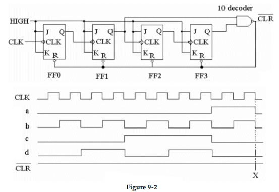
-The circuit in Figure 9- 2 is a(n)__________ .
A) two- bit asynchronous binary counter
B) eight- bit asynchronous binary flip- flop
C) four- bit asynchronous binary counter
D) three- bit synchronous binary counter
-The circuit in Figure 9- 2 is a(n)__________ .
A) two- bit asynchronous binary counter
B) eight- bit asynchronous binary flip- flop
C) four- bit asynchronous binary counter
D) three- bit synchronous binary counter
Question
?
-Which of the waveforms shown in Figure 9- 2 represents the output of FF2?
A) Waveform a
B) Waveform b
C) Waveform c
D) Waveform d
-Which of the waveforms shown in Figure 9- 2 represents the output of FF2?
A) Waveform a
B) Waveform b
C) Waveform c
D) Waveform d
Question
Question
? 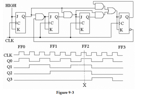
-The circuit shown in Figure 9- 3 represents a(n) __________ .
A) asynchronous BCD decade counter
B) synchronous BCD decade counter
C) BCD- to- decimal decoder
D) four- bit binary counter
-The circuit shown in Figure 9- 3 represents a(n) __________ .
A) asynchronous BCD decade counter
B) synchronous BCD decade counter
C) BCD- to- decimal decoder
D) four- bit binary counter
Question
?
-Referring to the waveforms in Figure 9- 3, what is the decimal count at point 'X'?
A) 7
B) 0110
C) 4
D) 11
-Referring to the waveforms in Figure 9- 3, what is the decimal count at point 'X'?
A) 7
B) 0110
C) 4
D) 11
Question
? 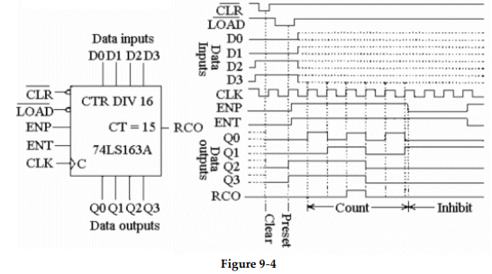
-What is the meaning of the label 'CTR DIV 16' on the 74LS163A diagram shown in Figure 9- 4?
A) The circuit is a four- bit, 16- state counter.
B) The circuit is a control device with 16 outputs.
C) The circuit is a hexadecimal converter.
D) The circuit is a 16- bit, four- state counter.
-What is the meaning of the label 'CTR DIV 16' on the 74LS163A diagram shown in Figure 9- 4?
A) The circuit is a four- bit, 16- state counter.
B) The circuit is a control device with 16 outputs.
C) The circuit is a hexadecimal converter.
D) The circuit is a 16- bit, four- state counter.
Question
?
-Which of the following statements is correct concerning Figure 9- 4?
A) Both the ENP and ENT terminals must be HIGH in order for the counter to cycle on the leading edge of the CLK input.
B) Both the active- LOW CLR and LOAD inputs must be LOW in order for the counter to cycle.
C) When the CLK input goes HIGH, the data on the DATA INPUT terminals is passed through to the DATA OUTPUT terminals.
D) The active- HIGH ENT and ENP inputs must be HIGH, while the active- LOW CLR and LOAD inputs must be LOW in order for the counter to cycle.
Question
Question
? 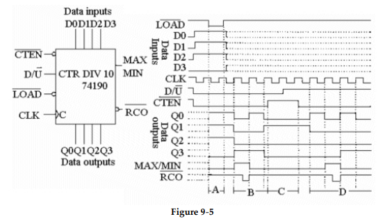
-What function does the counter shown in Figure 9- 5 perform during period B on the timing diagram?
A) Loading
B) Inhibited
C) Counting down
D) Counting up
-What function does the counter shown in Figure 9- 5 perform during period B on the timing diagram?
A) Loading
B) Inhibited
C) Counting down
D) Counting up
Question
?
-What function does the counter shown in Figure 9- 5 perform during period A on the timing diagram?
A) Loading
B) Counting down
C) Counting up
D) Inhibited
-What function does the counter shown in Figure 9- 5 perform during period A on the timing diagram?
A) Loading
B) Counting down
C) Counting up
D) Inhibited
Question
?
-During period D on the timing diagram in Figure 9- 5, the decimal count sequence is ________ .
A) 1, 0, 9, 8
B) 7, 8, 9, 1
C) 8, 9, 0, 1
D) 0, 1, 9, 8
-During period D on the timing diagram in Figure 9- 5, the decimal count sequence is ________ .
A) 1, 0, 9, 8
B) 7, 8, 9, 1
C) 8, 9, 0, 1
D) 0, 1, 9, 8
Question
?
-The counter in Figure 9- 5 is counting DOWN; when the count reaches zero, the MAX/MIN output will go ________.
A) HIGH
B) LOW
-The counter in Figure 9- 5 is counting DOWN; when the count reaches zero, the MAX/MIN output will go ________.
A) HIGH
B) LOW
Question
? 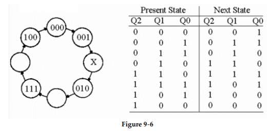
-The illustration shown in Figure 9- 6 is referred to as a _________.
A) state diagram
B) clock diagram
C) sequential diagram
D) cyclic state chart
-The illustration shown in Figure 9- 6 is referred to as a _________.
A) state diagram
B) clock diagram
C) sequential diagram
D) cyclic state chart
Question
?
-If the diagram shown in Figure 9- 6 represents a three- bit Gray code counter, what binary value would exist at 'X'?
A) 110
B) 101
C) 011
D) 010
-If the diagram shown in Figure 9- 6 represents a three- bit Gray code counter, what binary value would exist at 'X'?
A) 110
B) 101
C) 011
D) 010
Question
?
-The table shown in Figure 9- 6 is called a ________ .
A) sequential truth table
B) present state table
C) state diagram
D) next- state table
-The table shown in Figure 9- 6 is called a ________ .
A) sequential truth table
B) present state table
C) state diagram
D) next- state table
Question
? 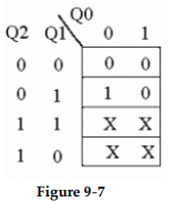
-The logic expression for the Karnaugh map in Figure 9- 7 is ________.
A)
B)
C)
D)
-The logic expression for the Karnaugh map in Figure 9- 7 is ________.
A)
B)
C)
D)
Question
?
-What is the significance of the Xs in the Karnaugh map shown in Figure 9- 7?
A) They must all be grouped together to form an output equation.
B) They can represent either ones or zeroes, as long as they are all the same.
C) They represent 'don't care' states.
D) They may be grouped with either the ones or the zeroes in the Karnaugh map.
Question
? 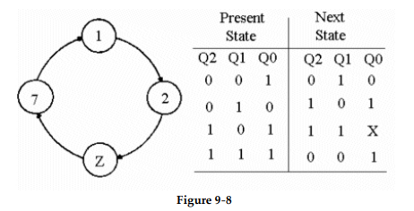
-Refer to Figure 9- 8. What value should 'X' represent in the state table?
A) 1
B) 0
-Refer to Figure 9- 8. What value should 'X' represent in the state table?
A) 1
B) 0
Question
?
-What value does 'Z' represent in Figure 9- 8?
A) 111
B) 3
C) 5
D) 4
-What value does 'Z' represent in Figure 9- 8?
A) 111
B) 3
C) 5
D) 4
Question
Question
? 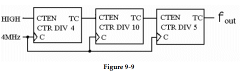
-What is the modulus of the counter shown in Figure 9- 9?
A) 0.005
B) 5000
C) 19
D) 200
-What is the modulus of the counter shown in Figure 9- 9?
A) 0.005
B) 5000
C) 19
D) 200
Question
?
-What is the output frequency of the counter in Figure 9- 9?
A) 210.5 kHz
B) 800 Hz
C) 4 MHz
D) 20 kHz
-What is the output frequency of the counter in Figure 9- 9?
A) 210.5 kHz
B) 800 Hz
C) 4 MHz
D) 20 kHz
Question
What decimal value is required to produce an output at 'X' in this circuit?
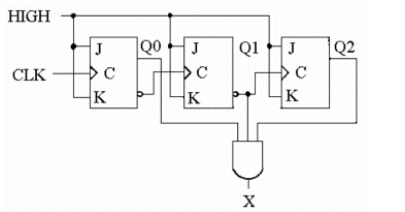
A) 1
B) 2
C) 5
D) 1 or 4
A) 1
B) 2
C) 5
D) 1 or 4
Question
? 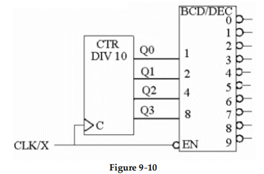
-The 'X' in the CLK/X input in Figure 9- 10 is normally called the _______ , and, in this example, is an active _______level.
A) ENABLE, HIGH
B) STROBE, LOW
C) STROBE, HIGH
D) NOT CLOCK, LOW
-The 'X' in the CLK/X input in Figure 9- 10 is normally called the _______ , and, in this example, is an active _______level.
A) ENABLE, HIGH
B) STROBE, LOW
C) STROBE, HIGH
D) NOT CLOCK, LOW
Question
?
-The purpose of the connection between 'C' of the 'CTR DIV 10' circuit and the 'EN' of the 'BCD/DEC' circuit in Figure 9- 10 is to _______ and is referred to as _______ .
A) reduce the number of inputs, enabling
B) speed up the counter, strobing
C) clock the counter, strobing
D) eliminate glitches, strobing
Question
Question
Question
? 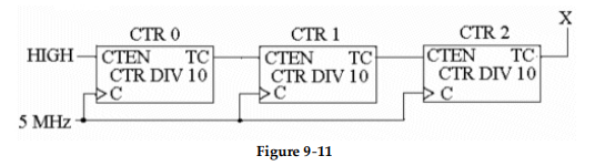
-The circuit in Figure 9- 11 is used for _________ and for the inputs shown, the DATA OUT will be _________ .
A) parallel- to- serial conversion, HIGH
B) demultiplexing, 0
C) multiplexing, 1
D) parallel- to- serial conversion, 0
-The circuit in Figure 9- 11 is used for _________ and for the inputs shown, the DATA OUT will be _________ .
A) parallel- to- serial conversion, HIGH
B) demultiplexing, 0
C) multiplexing, 1
D) parallel- to- serial conversion, 0
Question
?
-Refer to Figure 9- 11. The output of the counter is checked and found to be 50 kHz. Is the counter working correctly? If not, what could be wrong?
A) The counter is defective; there is probably a bad connection on the CTEN terminal of CTR0.
B) The counter is defective; an open exists somewhere between TC of CTR0 and CTEN of CTR1.
C) The counter is working correctly.
D) The counter is not working correctly; the TC of CTR1 is probably shorted to ground.
Question
?
-Refer to Figure 9- 11. The TC output of CTR0 shorts to ground; what will be the output frequency at 'X'?
A) 50 kHz
B) 0 Hz
C) 500 kHz
D) 5 kHz
-Refer to Figure 9- 11. The TC output of CTR0 shorts to ground; what will be the output frequency at 'X'?
A) 50 kHz
B) 0 Hz
C) 500 kHz
D) 5 kHz
Question
? 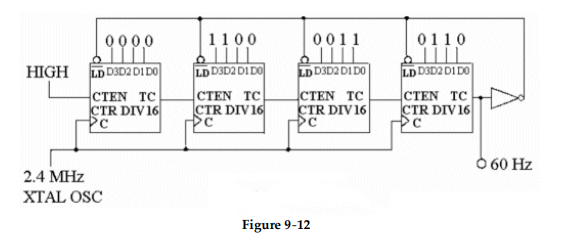
-Refer to Figure 9- 12. The circuit is used to derive a 60 Hz reference for a digital clock. After running for 24 hours the clock appears to be running 2 minutes and 18 seconds slow. What appears to be wrong with the circuit?
A) The error is very small and is to be expected of a circuit of this type; the clock should be regularly reset.
B) The modulus of the counter has decreased, causing the counter to produce a lower output reference signal for the clock.
C) The modulus of the counter has increased, causing a drop in the output frequency of the counter.
D) The XTAL OSC is probably cooling off too much at night and consequently slowing down; the XTAL OSC should be temperature compensated.
Question
?
-One of the most common and least expensive crystals available is the 3.58 MHz crystal used in color television sets. What hex value would have to be loaded into the counter in Figure 9- 12 in order to use the 3.58 MHz crystal to derive the 60Hz reference signal for the clock?
A) E912
B) 63C0
C) 16ED
D) E3C0

Unlock Deck
Sign up to unlock the cards in this deck!
Unlock Deck
Unlock Deck
1/50
Play
Full screen (f)
Deck 9: Counters
1
A state machine has a finite number of states that occur in random order.
False
2
The output from a Mealy state machine depends on its internal state and on external inputs.
True
3
A Moore state machine does not have a clock input.
False
4
The term synchronous refers to events that do not occur at the same time.
Unlock Deck
Unlock for access to all 50 flashcards in this deck.
Unlock Deck
k this deck
5
The term synchronous as applied to counter operations means that the counter is clocked so that each flip- flop in the counter is triggered at the same time.
Unlock Deck
Unlock for access to all 50 flashcards in this deck.
Unlock Deck
k this deck
6
Another term used to describe up/down counters is bidirectional.
Unlock Deck
Unlock for access to all 50 flashcards in this deck.
Unlock Deck
k this deck
7
Once an up/down counter begins its count sequence, it cannot be reversed.
Unlock Deck
Unlock for access to all 50 flashcards in this deck.
Unlock Deck
k this deck
8
Most sequential circuits contain a combinational logic section and a memory section.
Unlock Deck
Unlock for access to all 50 flashcards in this deck.
Unlock Deck
k this deck
9
Basic counters can be cascaded to increase the number of count states the counter can produce.
Unlock Deck
Unlock for access to all 50 flashcards in this deck.
Unlock Deck
k this deck
10
Counters are generally decoded in order to determine their count state.
Unlock Deck
Unlock for access to all 50 flashcards in this deck.
Unlock Deck
k this deck
11
In many cases, counters must be strobed in order to eliminate glitches.
Unlock Deck
Unlock for access to all 50 flashcards in this deck.
Unlock Deck
k this deck
12
The register output expression Q0 = D0 indicates that the output Q0 will assume the value of the D0 input on the clock pulse.
Unlock Deck
Unlock for access to all 50 flashcards in this deck.
Unlock Deck
k this deck
13
The dot extension .CLK is used to indicate that the register device is a clocked flip- flop.
Unlock Deck
Unlock for access to all 50 flashcards in this deck.
Unlock Deck
k this deck
14
Which type of state machine has a clock input?
A) Moore
B) State machines do not have clock inputs.
C) Mealy
D) Moore and Mealy
A) Moore
B) State machines do not have clock inputs.
C) Mealy
D) Moore and Mealy
Unlock Deck
Unlock for access to all 50 flashcards in this deck.
Unlock Deck
k this deck
15
Which of the following statements is true?
A) Asynchronous events are controlled by a clock.
B) Synchronous events do not need a clock to control them.
C) Only asynchronous events need a control clock.
D) Asynchronous events occur independently of the circuit clock.
A) Asynchronous events are controlled by a clock.
B) Synchronous events do not need a clock to control them.
C) Only asynchronous events need a control clock.
D) Asynchronous events occur independently of the circuit clock.
Unlock Deck
Unlock for access to all 50 flashcards in this deck.
Unlock Deck
k this deck
16
?
-The counter shown in Figure 9- 1 is a(n) __________ counter, and the correct output waveform for Q1 is__________ .
A) synchronous, Q1a
B) asynchronous, Q1b
C) asynchronous, Q1c
D) synchronous, Q1d
-The counter shown in Figure 9- 1 is a(n) __________ counter, and the correct output waveform for Q1 is__________ .
A) synchronous, Q1a
B) asynchronous, Q1b
C) asynchronous, Q1c
D) synchronous, Q1d
Unlock Deck
Unlock for access to all 50 flashcards in this deck.
Unlock Deck
k this deck
17
?
-An oscilloscope indicates that the circuit in Figure 9- 1 has no Q1 output signal. All J- K inputs are HIGH, the CLK signal is present and Q0 is toggling. The C input of FF1 is a constant LOW. What could be causing the problem?
A) The Q0 output should be connected to the J input of FFl.
B) The input of FF1 may be shorted to ground.
C) The output of FF0 may be shorted to ground.
D) The problem could be caused by either B or C.
Unlock Deck
Unlock for access to all 50 flashcards in this deck.
Unlock Deck
k this deck
18
Asynchronous counters are often called __________counters.
A) binary
B) flip- flop
C) ripple
D) toggle
A) binary
B) flip- flop
C) ripple
D) toggle
Unlock Deck
Unlock for access to all 50 flashcards in this deck.
Unlock Deck
k this deck
19
?
-The circuit in Figure 9- 2 is a(n)__________ .
A) two- bit asynchronous binary counter
B) eight- bit asynchronous binary flip- flop
C) four- bit asynchronous binary counter
D) three- bit synchronous binary counter
-The circuit in Figure 9- 2 is a(n)__________ .
A) two- bit asynchronous binary counter
B) eight- bit asynchronous binary flip- flop
C) four- bit asynchronous binary counter
D) three- bit synchronous binary counter
Unlock Deck
Unlock for access to all 50 flashcards in this deck.
Unlock Deck
k this deck
20
?
-Which of the waveforms shown in Figure 9- 2 represents the output of FF2?
A) Waveform a
B) Waveform b
C) Waveform c
D) Waveform d
-Which of the waveforms shown in Figure 9- 2 represents the output of FF2?
A) Waveform a
B) Waveform b
C) Waveform c
D) Waveform d
Unlock Deck
Unlock for access to all 50 flashcards in this deck.
Unlock Deck
k this deck
21
A decade counter counts from zero (0) through decimal __________.
A) 9
B) 15
C) 0
D) 10
A) 9
B) 15
C) 0
D) 10
Unlock Deck
Unlock for access to all 50 flashcards in this deck.
Unlock Deck
k this deck
22
?
-The circuit shown in Figure 9- 3 represents a(n) __________ .
A) asynchronous BCD decade counter
B) synchronous BCD decade counter
C) BCD- to- decimal decoder
D) four- bit binary counter
-The circuit shown in Figure 9- 3 represents a(n) __________ .
A) asynchronous BCD decade counter
B) synchronous BCD decade counter
C) BCD- to- decimal decoder
D) four- bit binary counter
Unlock Deck
Unlock for access to all 50 flashcards in this deck.
Unlock Deck
k this deck
23
?
-Referring to the waveforms in Figure 9- 3, what is the decimal count at point 'X'?
A) 7
B) 0110
C) 4
D) 11
-Referring to the waveforms in Figure 9- 3, what is the decimal count at point 'X'?
A) 7
B) 0110
C) 4
D) 11
Unlock Deck
Unlock for access to all 50 flashcards in this deck.
Unlock Deck
k this deck
24
?
-What is the meaning of the label 'CTR DIV 16' on the 74LS163A diagram shown in Figure 9- 4?
A) The circuit is a four- bit, 16- state counter.
B) The circuit is a control device with 16 outputs.
C) The circuit is a hexadecimal converter.
D) The circuit is a 16- bit, four- state counter.
-What is the meaning of the label 'CTR DIV 16' on the 74LS163A diagram shown in Figure 9- 4?
A) The circuit is a four- bit, 16- state counter.
B) The circuit is a control device with 16 outputs.
C) The circuit is a hexadecimal converter.
D) The circuit is a 16- bit, four- state counter.
Unlock Deck
Unlock for access to all 50 flashcards in this deck.
Unlock Deck
k this deck
25
?
-Which of the following statements is correct concerning Figure 9- 4?
A) Both the ENP and ENT terminals must be HIGH in order for the counter to cycle on the leading edge of the CLK input.
B) Both the active- LOW CLR and LOAD inputs must be LOW in order for the counter to cycle.
C) When the CLK input goes HIGH, the data on the DATA INPUT terminals is passed through to the DATA OUTPUT terminals.
D) The active- HIGH ENT and ENP inputs must be HIGH, while the active- LOW CLR and LOAD inputs must be LOW in order for the counter to cycle.
Unlock Deck
Unlock for access to all 50 flashcards in this deck.
Unlock Deck
k this deck
26
Which of the following statements best describes the operation of an UP/DOWN SYNCHRONOUS COUNTER?
A) The counter can count in either direction, but must continue in that direction once started.
B) In general, the counter can be reversed at any point in its counting sequence.
C) The counter can be reversed, but must be RESET before counting in the other direction.
D) The count sequence cannot be reversed, once it has begun, without first resetting the counter to zero.
Unlock Deck
Unlock for access to all 50 flashcards in this deck.
Unlock Deck
k this deck
27
?
-What function does the counter shown in Figure 9- 5 perform during period B on the timing diagram?
A) Loading
B) Inhibited
C) Counting down
D) Counting up
-What function does the counter shown in Figure 9- 5 perform during period B on the timing diagram?
A) Loading
B) Inhibited
C) Counting down
D) Counting up
Unlock Deck
Unlock for access to all 50 flashcards in this deck.
Unlock Deck
k this deck
28
?
-What function does the counter shown in Figure 9- 5 perform during period A on the timing diagram?
A) Loading
B) Counting down
C) Counting up
D) Inhibited
-What function does the counter shown in Figure 9- 5 perform during period A on the timing diagram?
A) Loading
B) Counting down
C) Counting up
D) Inhibited
Unlock Deck
Unlock for access to all 50 flashcards in this deck.
Unlock Deck
k this deck
29
?
-During period D on the timing diagram in Figure 9- 5, the decimal count sequence is ________ .
A) 1, 0, 9, 8
B) 7, 8, 9, 1
C) 8, 9, 0, 1
D) 0, 1, 9, 8
-During period D on the timing diagram in Figure 9- 5, the decimal count sequence is ________ .
A) 1, 0, 9, 8
B) 7, 8, 9, 1
C) 8, 9, 0, 1
D) 0, 1, 9, 8
Unlock Deck
Unlock for access to all 50 flashcards in this deck.
Unlock Deck
k this deck
30
?
-The counter in Figure 9- 5 is counting DOWN; when the count reaches zero, the MAX/MIN output will go ________.
A) HIGH
B) LOW
-The counter in Figure 9- 5 is counting DOWN; when the count reaches zero, the MAX/MIN output will go ________.
A) HIGH
B) LOW
Unlock Deck
Unlock for access to all 50 flashcards in this deck.
Unlock Deck
k this deck
31
?
-The illustration shown in Figure 9- 6 is referred to as a _________.
A) state diagram
B) clock diagram
C) sequential diagram
D) cyclic state chart
-The illustration shown in Figure 9- 6 is referred to as a _________.
A) state diagram
B) clock diagram
C) sequential diagram
D) cyclic state chart
Unlock Deck
Unlock for access to all 50 flashcards in this deck.
Unlock Deck
k this deck
32
?
-If the diagram shown in Figure 9- 6 represents a three- bit Gray code counter, what binary value would exist at 'X'?
A) 110
B) 101
C) 011
D) 010
-If the diagram shown in Figure 9- 6 represents a three- bit Gray code counter, what binary value would exist at 'X'?
A) 110
B) 101
C) 011
D) 010
Unlock Deck
Unlock for access to all 50 flashcards in this deck.
Unlock Deck
k this deck
33
?
-The table shown in Figure 9- 6 is called a ________ .
A) sequential truth table
B) present state table
C) state diagram
D) next- state table
-The table shown in Figure 9- 6 is called a ________ .
A) sequential truth table
B) present state table
C) state diagram
D) next- state table
Unlock Deck
Unlock for access to all 50 flashcards in this deck.
Unlock Deck
k this deck
34
?
-The logic expression for the Karnaugh map in Figure 9- 7 is ________.
A)
B)
C)
D)
-The logic expression for the Karnaugh map in Figure 9- 7 is ________.
A)
B)
C)
D)
Unlock Deck
Unlock for access to all 50 flashcards in this deck.
Unlock Deck
k this deck
35
?
-What is the significance of the Xs in the Karnaugh map shown in Figure 9- 7?
A) They must all be grouped together to form an output equation.
B) They can represent either ones or zeroes, as long as they are all the same.
C) They represent 'don't care' states.
D) They may be grouped with either the ones or the zeroes in the Karnaugh map.
Unlock Deck
Unlock for access to all 50 flashcards in this deck.
Unlock Deck
k this deck
36
?
-Refer to Figure 9- 8. What value should 'X' represent in the state table?
A) 1
B) 0
-Refer to Figure 9- 8. What value should 'X' represent in the state table?
A) 1
B) 0
Unlock Deck
Unlock for access to all 50 flashcards in this deck.
Unlock Deck
k this deck
37
?
-What value does 'Z' represent in Figure 9- 8?
A) 111
B) 3
C) 5
D) 4
-What value does 'Z' represent in Figure 9- 8?
A) 111
B) 3
C) 5
D) 4
Unlock Deck
Unlock for access to all 50 flashcards in this deck.
Unlock Deck
k this deck
38
Modulus refers to_________.
A) the modulus of elasticity, or the ability of a circuit to be stretched from one mode to another
B) an input on a counter that is used to set the counter state, such as UP/DOWN
C) a method used to fabricate decade counter units
D) the maximum number of states in a counter sequence
A) the modulus of elasticity, or the ability of a circuit to be stretched from one mode to another
B) an input on a counter that is used to set the counter state, such as UP/DOWN
C) a method used to fabricate decade counter units
D) the maximum number of states in a counter sequence
Unlock Deck
Unlock for access to all 50 flashcards in this deck.
Unlock Deck
k this deck
39
?
-What is the modulus of the counter shown in Figure 9- 9?
A) 0.005
B) 5000
C) 19
D) 200
-What is the modulus of the counter shown in Figure 9- 9?
A) 0.005
B) 5000
C) 19
D) 200
Unlock Deck
Unlock for access to all 50 flashcards in this deck.
Unlock Deck
k this deck
40
?
-What is the output frequency of the counter in Figure 9- 9?
A) 210.5 kHz
B) 800 Hz
C) 4 MHz
D) 20 kHz
-What is the output frequency of the counter in Figure 9- 9?
A) 210.5 kHz
B) 800 Hz
C) 4 MHz
D) 20 kHz
Unlock Deck
Unlock for access to all 50 flashcards in this deck.
Unlock Deck
k this deck
41
What decimal value is required to produce an output at 'X' in this circuit?
A) 1
B) 2
C) 5
D) 1 or 4
A) 1
B) 2
C) 5
D) 1 or 4
Unlock Deck
Unlock for access to all 50 flashcards in this deck.
Unlock Deck
k this deck
42
?
-The 'X' in the CLK/X input in Figure 9- 10 is normally called the _______ , and, in this example, is an active _______level.
A) ENABLE, HIGH
B) STROBE, LOW
C) STROBE, HIGH
D) NOT CLOCK, LOW
-The 'X' in the CLK/X input in Figure 9- 10 is normally called the _______ , and, in this example, is an active _______level.
A) ENABLE, HIGH
B) STROBE, LOW
C) STROBE, HIGH
D) NOT CLOCK, LOW
Unlock Deck
Unlock for access to all 50 flashcards in this deck.
Unlock Deck
k this deck
43
?
-The purpose of the connection between 'C' of the 'CTR DIV 10' circuit and the 'EN' of the 'BCD/DEC' circuit in Figure 9- 10 is to _______ and is referred to as _______ .
A) reduce the number of inputs, enabling
B) speed up the counter, strobing
C) clock the counter, strobing
D) eliminate glitches, strobing
Unlock Deck
Unlock for access to all 50 flashcards in this deck.
Unlock Deck
k this deck
44
In order to check the CLR function of a counter, which action should be taken?
A) Apply the active level to the CLR input and check all of the Q outputs to see if they are all in their reset state.
B) Connect the CLR to its correct active level while clocking the counter; check to make sure that all of the Q outputs are toggling.
C) Ground the CLR input and check to be sure that all of the Q outputs are LOW.
D) Connect the CLR input to Vcc and check to see if all of the Q outputs are HIGH.
Unlock Deck
Unlock for access to all 50 flashcards in this deck.
Unlock Deck
k this deck
45
Which of the following procedures would be used to check the parallel loading feature on a counter?
A) Apply HIGHs to all the DATA inputs, pulse the CLK and CLR inputs, and check to be sure that the Q outputs are all LOW.
B) Apply HIGHs to all the Q terminals, pulse the CLK and check to see if the DATA terminals now match the Q outputs.
C) Preset the LOAD inputs, set the CLR to its active level and check to see that the Q outputs match the values preset into the LOAD inputs.
D) Apply LOWs to the parallel DATA inputs, pulse the CLK input and check for LOWs on all the Q outputs.
Unlock Deck
Unlock for access to all 50 flashcards in this deck.
Unlock Deck
k this deck
46
?
-The circuit in Figure 9- 11 is used for _________ and for the inputs shown, the DATA OUT will be _________ .
A) parallel- to- serial conversion, HIGH
B) demultiplexing, 0
C) multiplexing, 1
D) parallel- to- serial conversion, 0
-The circuit in Figure 9- 11 is used for _________ and for the inputs shown, the DATA OUT will be _________ .
A) parallel- to- serial conversion, HIGH
B) demultiplexing, 0
C) multiplexing, 1
D) parallel- to- serial conversion, 0
Unlock Deck
Unlock for access to all 50 flashcards in this deck.
Unlock Deck
k this deck
47
?
-Refer to Figure 9- 11. The output of the counter is checked and found to be 50 kHz. Is the counter working correctly? If not, what could be wrong?
A) The counter is defective; there is probably a bad connection on the CTEN terminal of CTR0.
B) The counter is defective; an open exists somewhere between TC of CTR0 and CTEN of CTR1.
C) The counter is working correctly.
D) The counter is not working correctly; the TC of CTR1 is probably shorted to ground.
Unlock Deck
Unlock for access to all 50 flashcards in this deck.
Unlock Deck
k this deck
48
?
-Refer to Figure 9- 11. The TC output of CTR0 shorts to ground; what will be the output frequency at 'X'?
A) 50 kHz
B) 0 Hz
C) 500 kHz
D) 5 kHz
-Refer to Figure 9- 11. The TC output of CTR0 shorts to ground; what will be the output frequency at 'X'?
A) 50 kHz
B) 0 Hz
C) 500 kHz
D) 5 kHz
Unlock Deck
Unlock for access to all 50 flashcards in this deck.
Unlock Deck
k this deck
49
?
-Refer to Figure 9- 12. The circuit is used to derive a 60 Hz reference for a digital clock. After running for 24 hours the clock appears to be running 2 minutes and 18 seconds slow. What appears to be wrong with the circuit?
A) The error is very small and is to be expected of a circuit of this type; the clock should be regularly reset.
B) The modulus of the counter has decreased, causing the counter to produce a lower output reference signal for the clock.
C) The modulus of the counter has increased, causing a drop in the output frequency of the counter.
D) The XTAL OSC is probably cooling off too much at night and consequently slowing down; the XTAL OSC should be temperature compensated.
Unlock Deck
Unlock for access to all 50 flashcards in this deck.
Unlock Deck
k this deck
50
?
-One of the most common and least expensive crystals available is the 3.58 MHz crystal used in color television sets. What hex value would have to be loaded into the counter in Figure 9- 12 in order to use the 3.58 MHz crystal to derive the 60Hz reference signal for the clock?
A) E912
B) 63C0
C) 16ED
D) E3C0
Unlock Deck
Unlock for access to all 50 flashcards in this deck.
Unlock Deck
k this deck
Unlock Deck
Unlock for access to all 50 flashcards in this deck.


