
Introduction to Flight 7th Edition by John Anderson
Edition 7ISBN: 978-0073380247Introduction to Flight 7th Edition by John Anderson
Edition 7ISBN: 978-0073380247 Exercise 4
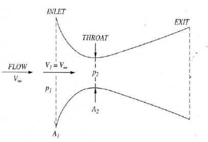
An instrument used to measure the airspeed on many early low-speed airplanes, principally during 1919 to 1930, was the venturi tube. This simple device is a convergent-divergent duct. (The front section's cross-sectional area A decreases in the flow direction, and the back section's cross-sectional area increases in the flow direction. Somewhere between the inlet and exit of the duct, there is a minimum area called the throat.) See figure below. Let A 1 and A 2 denote the inlet and throat areas, respectively. Let p 1 and p 2 be the pressures at the inlet and throat, respectively. The venturi tube is mounted at a specific location on the airplane (generally on the wing or near the front of the fuselage) where the inlet velocity V 1 is essentially the same as the free-stream velocity-that is, the velocity of the airplane through the air. With a knowledge of the area ratio A 2 /A 1 (a fixed design feature) and a measurement of the pressure difference p 1 - p 2 , we can determine the airplane's velocity. For example, assume
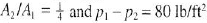 . If the airplane is flying at standard sea level, what is its velocity?
. If the airplane is flying at standard sea level, what is its velocity?Explanation Verified
4.4 From Bernoulli's equation,
![]() Also f...
Also f...
Introduction to Flight 7th Edition by John Anderson
Why don’t you like this exercise?
Other Minimum 8 character and maximum 255 character
Character 255


