Electronic Communication Systems 2nd Edition by Roy Blake
Edition 2ISBN: 978-0766826847Electronic Communication Systems 2nd Edition by Roy Blake
Edition 2ISBN: 978-0766826847 Exercise 11
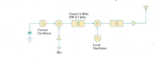
The block diagram of an SSB transmitter is shown in Figure 5.34. The local oscillator frequency is higher than the frequency at which the SSB signal is generated, and the difference between the two frequencies is used at the output.
(a) Choose a suitable frequency for the carrier oscillator if the transmitter is to produce a USB signal.
(b) What should be the frequency of the local oscillator if the (suppressed) carrier frequency at the antenna is to be exactly 30 MHz
(c) Suppose that the transmitter is modulated by a single sine-wave tone at 1 kHz. It is operating with a PEP of 100 W into a 50 load. Sketch the output in the time and frequency domains, showing all appropriate scales.
Figure 5.34
Explanation Verified
Refer to Figure 5.34 in the textbook for...
Electronic Communication Systems 2nd Edition by Roy Blake
Why don’t you like this exercise?
Other Minimum 8 character and maximum 255 character
Character 255


