Deck 3: Special-Purpose Diodes
Full screen (f)
Question
 Figure 4
Refer to Figure 4. The symbol for a varactor diode is voltage across the load is
A)(a)
B)(b)
C)(c)
D)(d)
Question
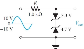 Figure 2
Refer to Figure 2. The maximum negative output voltage is
A)-8.0 V
B)-4.7 V
C)-5.4 V
D)-4.0 V
Question
 Figure 2
Refer to Figure 2. This circuit is a
A)voltage multiplier
B)clamper
C)limiter
D)regulator
Question
Question
Question
Question
Question
Question
Question
Question
Question
 Figure 1 VZ = 5.1 V at IZ = 49 mA, IZK = 1 mA, and ZZ = 7 ▲ over the range of current values.
Refer to Figure 1. Assume a 200 ▲ load resistor is connected across the output and the zener current is 49 mA. What is VIN?
A)14.9 V
B)24.7 V
C)20.0 V
D)12.2 V
Question
Question
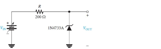 Figure 1 VZ = 5.1 V at IZ = 49 mA, IZK = 1 mA, and ZZ = 7 ▲ over the range of current values.
Refer to Figure 1. What setting of VIN will give an output closest to 5.1 V?
A)9.8 V
B)14.9 V
C)5.3 V
D)6.1 V
Question
Question
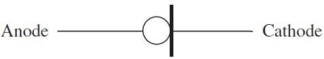 Figure 6
Refer to Figure 6. This is the schematic symbol for a
A)current regulator diode
B)Schottky diode
C)step- recovery diode
D)tunnel diode
Question
Question
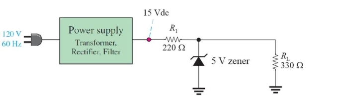 Figure 8
Refer to Figure 8. Assume a 150 ▲ resistor is put in parallel with RL. The new zener current will be
A)48 mA
B)100 mA
C)0 mA
D)3 mA
Question
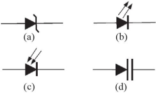 Figure 4
Refer to Figure 4. The symbol for an LED is output voltage will be
A)(a)
B)(b)
C)(c)
D)(d)
Question
 Figure 8
Refer to Figure 8. If the circuit is operating normally, the current in the zener diode is
A)30 mA
B)15 mA
C)45 mA
D)0 mA
Question
Question
Question
Question
Question
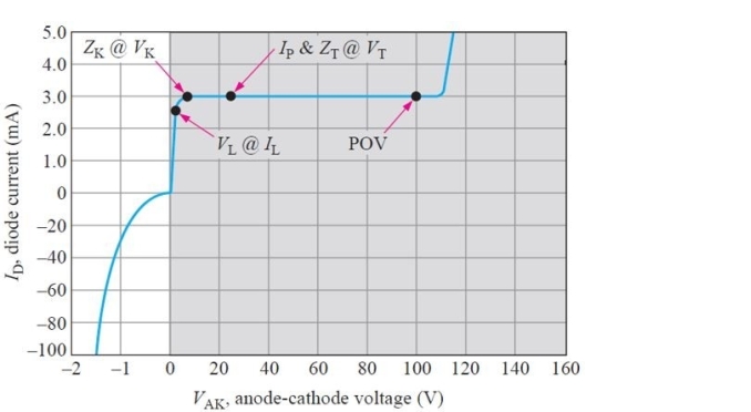 Figure 7
Refer to Figure 7. The curve is for a
A)Schottky diode
B)tunnel diode
C)current regulator diode
D)PIN diode
Question
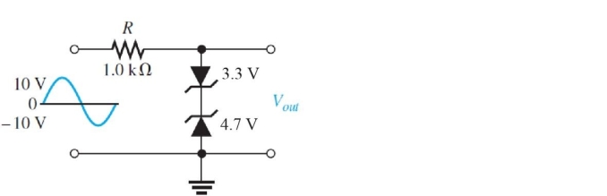 Figure 2
Refer to Figure 2. The maximum positive output voltage is
A)+4.0 V
B)+4.7 V
C)+8.0 V
D)+5.4 V
Question
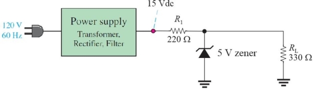 Figure 8
Refer Figure 8. If the zener diode is open, the output voltage will be
A)7.0 V
B)5.0 V
C)0 V
D)9.0 V
Question
 Figure 2
Refer to Figure 2. Assume the top diode is reversed. The circuit will
A)clip negative peaks below -8.0 V
B)clip positive peaks above +8.0 V
C)both A and B
D)none of the above
Question
Question
Question
Question
Question
Question
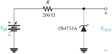 Figure 1 VZ = 5.1 V at IZ = 49 mA, IZK = 1 mA, and ZZ = 7 ▲ over the range of current values.
Refer to Figure 1. What is the output voltage if IZ = 20 mA?
A)4.9 V
B)5.1 V
C)4.8 V
D)5.0 V
Question
Question
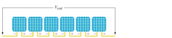 Figure 5 A solar panel
Refer to Figure 5. The cells are connected in series to increase
A)resistance
B)both current and voltage
C)current
D)voltage
Question
Question
Question
Question
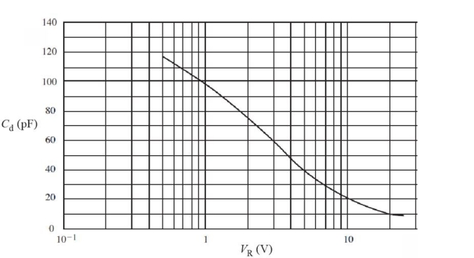 Figure 3 Bias curve for a typical varactor diode
Refer to Fig 3. For the varactor diode shown, the CR between 0.5 V and 10 V is approximately
A)18
B)11
C)5.9
D)1.5

Unlock Deck
Sign up to unlock the cards in this deck!
Unlock Deck
Unlock Deck
1/40
Play
Full screen (f)
Deck 3: Special-Purpose Diodes
1
Figure 4Refer to Figure 4. The symbol for a varactor diode is voltage across the load is
A)(a)
B)(b)
C)(c)
D)(d)
B
2
Figure 2Refer to Figure 2. The maximum negative output voltage is
A)-8.0 V
B)-4.7 V
C)-5.4 V
D)-4.0 V
D
3
Figure 2Refer to Figure 2. This circuit is a
A)voltage multiplier
B)clamper
C)limiter
D)regulator
C
4
A Schottky diode is primarily used as a
A)regulator
B)fast switching diode
C)low- frequency rectifier
D)variable capacitor
A)regulator
B)fast switching diode
C)low- frequency rectifier
D)variable capacitor
Unlock Deck
Unlock for access to all 40 flashcards in this deck.
Unlock Deck
k this deck
5
When a zener diode is forward biased, the voltage drop will be approximately
A)0.7 V
B)VZ + 0.7 V
C)VZ - 0.7 V
D)VZ
A)0.7 V
B)VZ + 0.7 V
C)VZ - 0.7 V
D)VZ
Unlock Deck
Unlock for access to all 40 flashcards in this deck.
Unlock Deck
k this deck
6
Reverse leakage current for a zener diode is specified
A)at a voltage that is less than the knee voltage
B)in reverse breakdown
C)at the knee voltage
D)none of the above
A)at a voltage that is less than the knee voltage
B)in reverse breakdown
C)at the knee voltage
D)none of the above
Unlock Deck
Unlock for access to all 40 flashcards in this deck.
Unlock Deck
k this deck
7
An OLED produces light by a process called
A)avalanche light emission
B)organic light emission
C)photonic light emission
D)electrophosphorescence
A)avalanche light emission
B)organic light emission
C)photonic light emission
D)electrophosphorescence
Unlock Deck
Unlock for access to all 40 flashcards in this deck.
Unlock Deck
k this deck
8
An application for an infrared diode is
A)traffic lights
B)in seven- segment displays
C)in a remote control for TV
D)all of the above
A)traffic lights
B)in seven- segment displays
C)in a remote control for TV
D)all of the above
Unlock Deck
Unlock for access to all 40 flashcards in this deck.
Unlock Deck
k this deck
9
In maximum power point tracking, maximum power is obtained by adjusting the
A)internal resistance
B)temperature
C)load resistance
D)bias voltage
A)internal resistance
B)temperature
C)load resistance
D)bias voltage
Unlock Deck
Unlock for access to all 40 flashcards in this deck.
Unlock Deck
k this deck
10
A photodiode can be controlled by light intensity to form a variable
A)capacitive device
B)resistance device
C)light source
D)all of the above
A)capacitive device
B)resistance device
C)light source
D)all of the above
Unlock Deck
Unlock for access to all 40 flashcards in this deck.
Unlock Deck
k this deck
11
Assume the frequency of a resonant circuit is varied with a varactor that has a minimum capacitance of 5 pF and a maximum capacitance of 50 pF. The ratio of highest to lowest frequency the circuit can tune is
A)greater than 10
B)10
C)less than 10
A)greater than 10
B)10
C)less than 10
Unlock Deck
Unlock for access to all 40 flashcards in this deck.
Unlock Deck
k this deck
12
Figure 1 VZ = 5.1 V at IZ = 49 mA, IZK = 1 mA, and ZZ = 7 ▲ over the range of current values.Refer to Figure 1. Assume a 200 ▲ load resistor is connected across the output and the zener current is 49 mA. What is VIN?
A)14.9 V
B)24.7 V
C)20.0 V
D)12.2 V
Unlock Deck
Unlock for access to all 40 flashcards in this deck.
Unlock Deck
k this deck
13
Compared to incandescent lamps, LEDs are
A)more efficient
B)have a longer lifetime
C)both A and B
D)none of the above
A)more efficient
B)have a longer lifetime
C)both A and B
D)none of the above
Unlock Deck
Unlock for access to all 40 flashcards in this deck.
Unlock Deck
k this deck
14
Figure 1 VZ = 5.1 V at IZ = 49 mA, IZK = 1 mA, and ZZ = 7 ▲ over the range of current values.Refer to Figure 1. What setting of VIN will give an output closest to 5.1 V?
A)9.8 V
B)14.9 V
C)5.3 V
D)6.1 V
Unlock Deck
Unlock for access to all 40 flashcards in this deck.
Unlock Deck
k this deck
15
In an IC regulator, an internal zener diode is used as a
A)reference
B)control element
C)feedback element
D)all of the above
A)reference
B)control element
C)feedback element
D)all of the above
Unlock Deck
Unlock for access to all 40 flashcards in this deck.
Unlock Deck
k this deck
16
Figure 6Refer to Figure 6. This is the schematic symbol for a
A)current regulator diode
B)Schottky diode
C)step- recovery diode
D)tunnel diode
Unlock Deck
Unlock for access to all 40 flashcards in this deck.
Unlock Deck
k this deck
17
A reverse- biased PIN diode acts like a
A)constant capacitance
B)variable resistance
C)constant current source
D)constant voltage source
A)constant capacitance
B)variable resistance
C)constant current source
D)constant voltage source
Unlock Deck
Unlock for access to all 40 flashcards in this deck.
Unlock Deck
k this deck
18
Figure 8Refer to Figure 8. Assume a 150 ▲ resistor is put in parallel with RL. The new zener current will be
A)48 mA
B)100 mA
C)0 mA
D)3 mA
Unlock Deck
Unlock for access to all 40 flashcards in this deck.
Unlock Deck
k this deck
19
Figure 4Refer to Figure 4. The symbol for an LED is output voltage will be
A)(a)
B)(b)
C)(c)
D)(d)
Unlock Deck
Unlock for access to all 40 flashcards in this deck.
Unlock Deck
k this deck
20
Figure 8Refer to Figure 8. If the circuit is operating normally, the current in the zener diode is
A)30 mA
B)15 mA
C)45 mA
D)0 mA
Unlock Deck
Unlock for access to all 40 flashcards in this deck.
Unlock Deck
k this deck
21
Power dissipation in a zener diode is the product of zener voltage and the current in the zener.
Unlock Deck
Unlock for access to all 40 flashcards in this deck.
Unlock Deck
k this deck
22
Typically, the VF for an LED is between
A)1.2 V and 3.2 V
B)3.2 V and 6.5 V
C)0 V and 0.6 V
D)0.6 V and 1.2 V
A)1.2 V and 3.2 V
B)3.2 V and 6.5 V
C)0 V and 0.6 V
D)0.6 V and 1.2 V
Unlock Deck
Unlock for access to all 40 flashcards in this deck.
Unlock Deck
k this deck
23
The crystalline solar cell converts sunlight to electricity using the photovoltaic effect.
Unlock Deck
Unlock for access to all 40 flashcards in this deck.
Unlock Deck
k this deck
24
Zener impedance is defined as
A)VZK/IZK
B)VZM/IZM
C)OVZ/OIZ
D)VZ/IZ
A)VZK/IZK
B)VZM/IZM
C)OVZ/OIZ
D)VZ/IZ
Unlock Deck
Unlock for access to all 40 flashcards in this deck.
Unlock Deck
k this deck
25
Figure 7Refer to Figure 7. The curve is for a
A)Schottky diode
B)tunnel diode
C)current regulator diode
D)PIN diode
Unlock Deck
Unlock for access to all 40 flashcards in this deck.
Unlock Deck
k this deck
26
Figure 2Refer to Figure 2. The maximum positive output voltage is
A)+4.0 V
B)+4.7 V
C)+8.0 V
D)+5.4 V
Unlock Deck
Unlock for access to all 40 flashcards in this deck.
Unlock Deck
k this deck
27
Figure 8Refer Figure 8. If the zener diode is open, the output voltage will be
A)7.0 V
B)5.0 V
C)0 V
D)9.0 V
Unlock Deck
Unlock for access to all 40 flashcards in this deck.
Unlock Deck
k this deck
28
Figure 2Refer to Figure 2. Assume the top diode is reversed. The circuit will
A)clip negative peaks below -8.0 V
B)clip positive peaks above +8.0 V
C)both A and B
D)none of the above
Unlock Deck
Unlock for access to all 40 flashcards in this deck.
Unlock Deck
k this deck
29
LED color is determined primarily by the
A)particular semiconductor and impurities added
B)color of the plastic covering
C)size of the diode
D)amount of forward current
A)particular semiconductor and impurities added
B)color of the plastic covering
C)size of the diode
D)amount of forward current
Unlock Deck
Unlock for access to all 40 flashcards in this deck.
Unlock Deck
k this deck
30
Photodiodes and varactor diodes are normally operated with reverse- bias.
Unlock Deck
Unlock for access to all 40 flashcards in this deck.
Unlock Deck
k this deck
31
A diode with a negative resistance characteristic is a varactor diode.
Unlock Deck
Unlock for access to all 40 flashcards in this deck.
Unlock Deck
k this deck
32
In a silicon solar cell, sunlight
A)creates electron- hole pairs
B)increases the resistance of the cell
C)produces a useable voltage of 5- 6 V across the cell
D)all of the above
A)creates electron- hole pairs
B)increases the resistance of the cell
C)produces a useable voltage of 5- 6 V across the cell
D)all of the above
Unlock Deck
Unlock for access to all 40 flashcards in this deck.
Unlock Deck
k this deck
33
A zener diode is also called a tuning diode.
Unlock Deck
Unlock for access to all 40 flashcards in this deck.
Unlock Deck
k this deck
34
Figure 1 VZ = 5.1 V at IZ = 49 mA, IZK = 1 mA, and ZZ = 7 ▲ over the range of current values.Refer to Figure 1. What is the output voltage if IZ = 20 mA?
A)4.9 V
B)5.1 V
C)4.8 V
D)5.0 V
Unlock Deck
Unlock for access to all 40 flashcards in this deck.
Unlock Deck
k this deck
35
The forward voltage across an LED is considerably less than for a silicon diode.
Unlock Deck
Unlock for access to all 40 flashcards in this deck.
Unlock Deck
k this deck
36
Figure 5 A solar panelRefer to Figure 5. The cells are connected in series to increase
A)resistance
B)both current and voltage
C)current
D)voltage
Unlock Deck
Unlock for access to all 40 flashcards in this deck.
Unlock Deck
k this deck
37
Different color LEDs require different forward voltages to operate.
Unlock Deck
Unlock for access to all 40 flashcards in this deck.
Unlock Deck
k this deck
38
A 1N4742A has a maximum power rating of 1.0 W at 50 °C. The derating factor is 9.67 mW/°C. If it is operated at 70 °C, the maximum power is
A)0.8 W
B)1.1 W
C)0.9 W
D)1.2 W
A)0.8 W
B)1.1 W
C)0.9 W
D)1.2 W
Unlock Deck
Unlock for access to all 40 flashcards in this deck.
Unlock Deck
k this deck
39
An application for tunnel diodes is
A)as rectifiers
B)in high- frequency oscillators
C)in switching circuits
D)as variable capacitors
A)as rectifiers
B)in high- frequency oscillators
C)in switching circuits
D)as variable capacitors
Unlock Deck
Unlock for access to all 40 flashcards in this deck.
Unlock Deck
k this deck
40
Figure 3 Bias curve for a typical varactor diodeRefer to Fig 3. For the varactor diode shown, the CR between 0.5 V and 10 V is approximately
A)18
B)11
C)5.9
D)1.5
Unlock Deck
Unlock for access to all 40 flashcards in this deck.
Unlock Deck
k this deck
Unlock Deck
Unlock for access to all 40 flashcards in this deck.


