Deck 14: Special-Purpose Integrated Circuits
Full screen (f)
Question
Question
 Figure 2 Assume the bias current is 125 µA and gm = 16 µS/µA.
Refer to Figure 2. If the power supplies have a lower voltage, the gain is
A)higher
B)lower
C)unaffected
Question

Refer to Figure 5. To change this to an antilog amplifier,
A)exchange the diode and R1
B)reverse the inputs on the op- amp
C)reverse the diode (anode and cathode)and reduce the value of R1
D)reverse the diode (anode and cathode)
Question
Question
Question
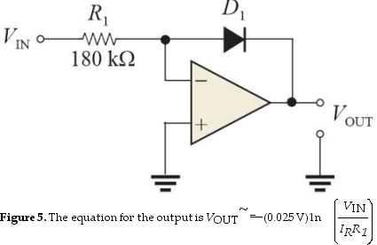
Refer to Figure 5. If the input is 3.0 V and IR = 50 nA, VOUT will be
A)-325 mV
B)-550 mV
C)-145 mV
D)none of the above
Question
Question
 Figure 6
Refer to Figure 6(a). Assume S was momentarily closed and Vin is connected to a +3.0 VDC source. The voltage at the inverting input is
A)3.7 V
B)2.3 V
C)-0.7 V
D)3.0 V
Question
Question
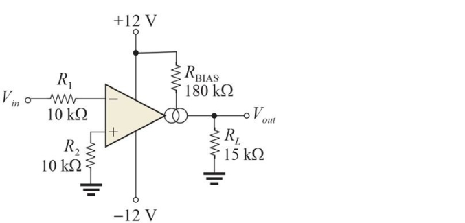 Figure 2 Assume the bias current is 125 µA and gm = 16 µS/µA.
Refer to Figure 2. The voltage gain is
A)8.2
B)16
C)30
D)1.9
Question
Question
Question
Question
Question
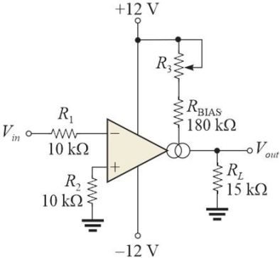 Figure 3
Refer to Figure 3. This purpose of R3 is to adjust the
A)gain
B)bandwidth
C)linearity
D)all of the above
Question
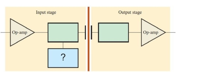 Figure 1 A capacitively coupled isolation amplifier
Refer to Figure 1. The box with the ? represents a
A)sinusoidal oscillator
B)pulse generator
C)modulator
D)sawtooth generator
Question
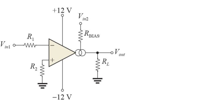 Figure 4 The circuit is a modulator for an audio signal.
Refer to Figure 4. The input at Vin1 is the _ and the input to the input at Vin2 is the .
A)audio signal, high- frequency oscillator
B)high- frequency oscillator, audio signal
C)either A or B will work
D)none of the above
Question
Figure 6Refer to Figure 6(b). A shorted load, RL, is likely to cause
A)excessive current in R2
B)the op- amp to fail
C)both of the above
D)none of the above
Question
 Figure 6
Refer to Figure 6(a). The circuit is
A)a peak detector
B)an antilog amplifier
C)a clamping circuit
D)a current source
Question
 Figure 6
Refer to Figure 6(b). The circuit is
A)a current source
B)an antilog amplifier
C)a clamping circuit
D)a peak detector
Question
Question
Question
 Figure 6
Refer to Figure 6(b). The current in RL is
A)5.1 mA
B)9.9 mA
C)23 mA
D)2.6 mA
Question
Question
Question
Question
Question
Question
 Figure 6
Refer to Figure 6(b). If the zener is open, the output current will be
A)7.5 mA
B)6.8 mA
C)15 mA
D)1.3 mA
Question
Question
Question
Question
Question
Question

Unlock Deck
Sign up to unlock the cards in this deck!
Unlock Deck
Unlock Deck
1/35
Play
Full screen (f)
Deck 14: Special-Purpose Integrated Circuits
1
Assume there is a phase shift between two common- mode signals. This can
A)increase the common mode voltage
B)lower the overall gain
C)create a differential voltage
D)all of the above
A)increase the common mode voltage
B)lower the overall gain
C)create a differential voltage
D)all of the above
C
2
Figure 2 Assume the bias current is 125 µA and gm = 16 µS/µA.Refer to Figure 2. If the power supplies have a lower voltage, the gain is
A)higher
B)lower
C)unaffected
B
3
Refer to Figure 5. To change this to an antilog amplifier,
A)exchange the diode and R1
B)reverse the inputs on the op- amp
C)reverse the diode (anode and cathode)and reduce the value of R1
D)reverse the diode (anode and cathode)
A
4
An ISO124 isolation amplifier has an internal oscillator of 500 kHz. The oscillator signal
A)is on a separate output
B)is filtered from the output by the user
C)is filtered from the output by the manufacturer
D)is added to the output signal
A)is on a separate output
B)is filtered from the output by the user
C)is filtered from the output by the manufacturer
D)is added to the output signal
Unlock Deck
Unlock for access to all 35 flashcards in this deck.
Unlock Deck
k this deck
5
With logarithmic signal compression,
A)all amplitudes are reduced by the same percentage
B)large amplitudes are attenuated more than small amplitudes
C)all amplitudes are reduced to a fixed value
D)none of the above
A)all amplitudes are reduced by the same percentage
B)large amplitudes are attenuated more than small amplitudes
C)all amplitudes are reduced to a fixed value
D)none of the above
Unlock Deck
Unlock for access to all 35 flashcards in this deck.
Unlock Deck
k this deck
6
Refer to Figure 5. If the input is 3.0 V and IR = 50 nA, VOUT will be
A)-325 mV
B)-550 mV
C)-145 mV
D)none of the above
Unlock Deck
Unlock for access to all 35 flashcards in this deck.
Unlock Deck
k this deck
7
To avoid very large capacitors in a capacitively coupled isolation amplifier, the amplifier can use
A)modulation/demodulation
B)signal compression
C)a differential amplifier
D)dc coupling
A)modulation/demodulation
B)signal compression
C)a differential amplifier
D)dc coupling
Unlock Deck
Unlock for access to all 35 flashcards in this deck.
Unlock Deck
k this deck
8
Figure 6Refer to Figure 6(a). Assume S was momentarily closed and Vin is connected to a +3.0 VDC source. The voltage at the inverting input is
A)3.7 V
B)2.3 V
C)-0.7 V
D)3.0 V
Unlock Deck
Unlock for access to all 35 flashcards in this deck.
Unlock Deck
k this deck
9
Isolation amplifiers can isolate the input and output by
A)transformer coupling
B)grounding both input and output to a common ground
C)both A and B
D)none of the above
A)transformer coupling
B)grounding both input and output to a common ground
C)both A and B
D)none of the above
Unlock Deck
Unlock for access to all 35 flashcards in this deck.
Unlock Deck
k this deck
10
Figure 2 Assume the bias current is 125 µA and gm = 16 µS/µA.Refer to Figure 2. The voltage gain is
A)8.2
B)16
C)30
D)1.9
Unlock Deck
Unlock for access to all 35 flashcards in this deck.
Unlock Deck
k this deck
11
An OTA with a transconductance of 2000 µS has a load resistance of 5 k▲. If the input voltage is 300 mV, the output voltage is
A)1.5 V
B)5.0 V
C)7.5 V
D)3.0 V
A)1.5 V
B)5.0 V
C)7.5 V
D)3.0 V
Unlock Deck
Unlock for access to all 35 flashcards in this deck.
Unlock Deck
k this deck
12
The bandwidth of a typical instrumentation amplifier is
A)depends on the input signal amplitude
B)set by an external resistor
C)independent of the gain
D)lower at high gain
A)depends on the input signal amplitude
B)set by an external resistor
C)independent of the gain
D)lower at high gain
Unlock Deck
Unlock for access to all 35 flashcards in this deck.
Unlock Deck
k this deck
13
The amount of bias current for an OTA changes the
A)transconductance
B)output resistance
C)input resistance
D)all of the above
A)transconductance
B)output resistance
C)input resistance
D)all of the above
Unlock Deck
Unlock for access to all 35 flashcards in this deck.
Unlock Deck
k this deck
14
A log amplifier is used for
A)linearization of certain signals
B)signal compression
C)certain analog arithmetic operations
D)all of the above
A)linearization of certain signals
B)signal compression
C)certain analog arithmetic operations
D)all of the above
Unlock Deck
Unlock for access to all 35 flashcards in this deck.
Unlock Deck
k this deck
15
Figure 3Refer to Figure 3. This purpose of R3 is to adjust the
A)gain
B)bandwidth
C)linearity
D)all of the above
Unlock Deck
Unlock for access to all 35 flashcards in this deck.
Unlock Deck
k this deck
16
Figure 1 A capacitively coupled isolation amplifierRefer to Figure 1. The box with the ? represents a
A)sinusoidal oscillator
B)pulse generator
C)modulator
D)sawtooth generator
Unlock Deck
Unlock for access to all 35 flashcards in this deck.
Unlock Deck
k this deck
17
Figure 4 The circuit is a modulator for an audio signal.Refer to Figure 4. The input at Vin1 is the _ and the input to the input at Vin2 is the .
A)audio signal, high- frequency oscillator
B)high- frequency oscillator, audio signal
C)either A or B will work
D)none of the above
Unlock Deck
Unlock for access to all 35 flashcards in this deck.
Unlock Deck
k this deck
18
Figure 6Refer to Figure 6(b). A shorted load, RL, is likely to cause
A)excessive current in R2
B)the op- amp to fail
C)both of the above
D)none of the above
Unlock Deck
Unlock for access to all 35 flashcards in this deck.
Unlock Deck
k this deck
19
Figure 6Refer to Figure 6(a). The circuit is
A)a peak detector
B)an antilog amplifier
C)a clamping circuit
D)a current source
Unlock Deck
Unlock for access to all 35 flashcards in this deck.
Unlock Deck
k this deck
20
Figure 6Refer to Figure 6(b). The circuit is
A)a current source
B)an antilog amplifier
C)a clamping circuit
D)a peak detector
Unlock Deck
Unlock for access to all 35 flashcards in this deck.
Unlock Deck
k this deck
21
An excellent way to reduce leakage current on the input lines is to
A)connect an inductor in parallel with the stray capacitance
B)ground the shield
C)connect the common- mode signal to the shield
D)connect the output signal to the shield
A)connect an inductor in parallel with the stray capacitance
B)ground the shield
C)connect the common- mode signal to the shield
D)connect the output signal to the shield
Unlock Deck
Unlock for access to all 35 flashcards in this deck.
Unlock Deck
k this deck
22
An instrumentation amplifier should have high CMRR.
Unlock Deck
Unlock for access to all 35 flashcards in this deck.
Unlock Deck
k this deck
23
Figure 6Refer to Figure 6(b). The current in RL is
A)5.1 mA
B)9.9 mA
C)23 mA
D)2.6 mA
Unlock Deck
Unlock for access to all 35 flashcards in this deck.
Unlock Deck
k this deck
24
The purpose of guarding with an instrumentation amplifier is to
A)reduce radiated signal loss
B)provide a path to shunt high frequency noise to ground
C)avoid a safety hazard with exposed wires
D)reduce the effects of distributed capacitance
A)reduce radiated signal loss
B)provide a path to shunt high frequency noise to ground
C)avoid a safety hazard with exposed wires
D)reduce the effects of distributed capacitance
Unlock Deck
Unlock for access to all 35 flashcards in this deck.
Unlock Deck
k this deck
25
An OTA has
A)fixed gain
B)differential input terminals
C)low output resistance
D)all of the above
A)fixed gain
B)differential input terminals
C)low output resistance
D)all of the above
Unlock Deck
Unlock for access to all 35 flashcards in this deck.
Unlock Deck
k this deck
26
The classic three- op- amp instrumentation amplifier will have a differential gain of 1 if RG is not connected.
Unlock Deck
Unlock for access to all 35 flashcards in this deck.
Unlock Deck
k this deck
27
An OTA is a current- to- voltage amplifier.
Unlock Deck
Unlock for access to all 35 flashcards in this deck.
Unlock Deck
k this deck
28
An isolation amplifier requires two separate power supplies.
Unlock Deck
Unlock for access to all 35 flashcards in this deck.
Unlock Deck
k this deck
29
Figure 6Refer to Figure 6(b). If the zener is open, the output current will be
A)7.5 mA
B)6.8 mA
C)15 mA
D)1.3 mA
Unlock Deck
Unlock for access to all 35 flashcards in this deck.
Unlock Deck
k this deck
30
The output signal from an isolation amplifier is a
A)dc level representing the peak input signal
B)pulse- width modulated signal
C)replica of the input
D)an amplitude modulated signal
A)dc level representing the peak input signal
B)pulse- width modulated signal
C)replica of the input
D)an amplitude modulated signal
Unlock Deck
Unlock for access to all 35 flashcards in this deck.
Unlock Deck
k this deck
31
A typical application for an instrumentation amplifier is
A)interfacing a transducer
B)impedance matching
C)wave- shaping
D)all of the above
A)interfacing a transducer
B)impedance matching
C)wave- shaping
D)all of the above
Unlock Deck
Unlock for access to all 35 flashcards in this deck.
Unlock Deck
k this deck
32
Audio power amplifiers typically have a bandwidth from 3 kHz to 30 kHz.
Unlock Deck
Unlock for access to all 35 flashcards in this deck.
Unlock Deck
k this deck
33
An OTA is often used to isolate a sensitive input from high voltage.
Unlock Deck
Unlock for access to all 35 flashcards in this deck.
Unlock Deck
k this deck
34
Some instrumentation amplifiers can set gain with a binary input.
Unlock Deck
Unlock for access to all 35 flashcards in this deck.
Unlock Deck
k this deck
35
The logarithm of a number is the power to which a base is raised to obtain the number.
Unlock Deck
Unlock for access to all 35 flashcards in this deck.
Unlock Deck
k this deck
Unlock Deck
Unlock for access to all 35 flashcards in this deck.


