Deck 15: Active Filters
Full screen (f)
Question
 Figure 4 A test of a filter using an oscilloscope
Refer to Figure 4. The signal on the X channel of the oscilloscope is a(n)
A)sawtooth
B)continuous frequency sinusoidal wave
C)amplitude modulated frequency
D)constant amplitude swept frequency
Question
Question
Question
 Figure 1 Stage 1: DF = 1.848 and R1/R2 = 0.152; stage 2: DF = 0.765 and R3/R4 =1.235.
Refer to Figure 1 with values as given. R3 should have a value of
A)1.8 k▲
B)1.5 k▲
C)1.2 k▲
D)none of the above
Question
Question
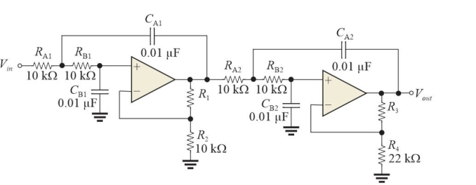 Figure 1 Stage 1: DF = 1.848 and R1/R2 = 0.152; stage 2: DF = 0.765 and R3/R4 =1.235.
Refer to Figure 1 with values as given. R1 should have a value of
A)1.2 k▲
B)1.8 k▲
C)1.5 k▲
D)none of the above
Question
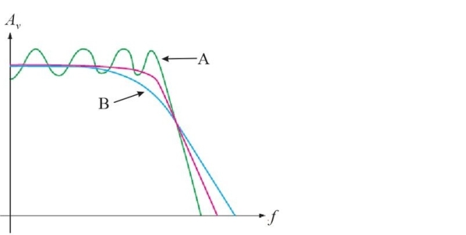 Figure 5 Response curve for three different filters
Refer to Figure 5. The response labeled "A" represents a
A)Butterworth response
B)Bessel response
C)Chebyshev response
D)none of the above
Question
Question
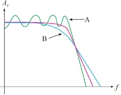 Figure 5 Response curve for three different filters
Refer to Figure 5. The response labeled "B" represents a
A)Butterworth response
B)Bessel response
C)Chebyshev response
D)none of the above
Question
 Figure 2 Note that the capacitors have different values.
Refer to Figure 2. The fc for the first section is
A)800 Hz
B)160 Hz
C)80 Hz
D)1.6 kHz
Question
 Figure 3
Refer to Figure 3. This type of filter is called a
A)biquad filter
B)Sallen- Key filter
C)multiple- feedback filter
D)state- variable filter
Question
Question
Question
Question
Figure 1 Stage 1: DF = 1.848 and R1/R2 = 0.152; stage 2: DF = 0.765 and R3/R4 =1.235.Refer to Figure 1. Assume Vin = 1.0 Vpp sine wave at 20 kHz. At this frequency, Vout is approximately
A)1.0 Vpp
B)10 mVpp
C)1.0 mVpp
D)100 µVpp
Question
 Figure 2 Note that the capacitors have different values.
Refer to Figure 2. Assume the capacitors in section 1 are made larger. This change will
A)decrease the bandwidth
B)increase the bandwidth
C)not affect the bandwidth
Question
Figure 4 A test of a filter using an oscilloscopeRefer to Figure 4. The block with the ? on it represents a
A)low- pass filter
B)impedance matching circuit
C)detector
D)amplifier
Question
 Figure 3
Refer to Figure 3. An advantage of this type of filter is that it
A)the low and high- pass outputs are equivalent to a 4- pole filter
B)can be optimized for all three outputs
C)the bandpass output can have a very high Q
D)all of the above
Question
Question
 Figure 4 A test of a filter using an oscilloscope
Refer to Figure 4. The input signal to the filter (Vin)is a(n)
A)continuous frequency sinusoidal wave
B)amplitude modulated frequency
C)constant amplitude swept frequency
D)sawtooth
Question
 Figure 1 Stage 1: DF = 1.848 and R1/R2 = 0.152; stage 2: DF = 0.765 and R3/R4 =1.235.
Refer to Figure 1. The type of filter is a
A)low- pass Sallen- Key filter
B)high- pass Sallen- Key filter
C)low- pass biquad filter
D)high- pass biquad filter
Question
 Figure 1 Stage 1: DF = 1.848 and R1/R2 = 0.152; stage 2: DF = 0.765 and R3/R4 =1.235.
Refer to Figure 1. The ideal roll- off rate is
A)-120 dB/decade
B)-80 dB/decade
C)-40 dB/decade
D)-20 dB/decade
Question
Question
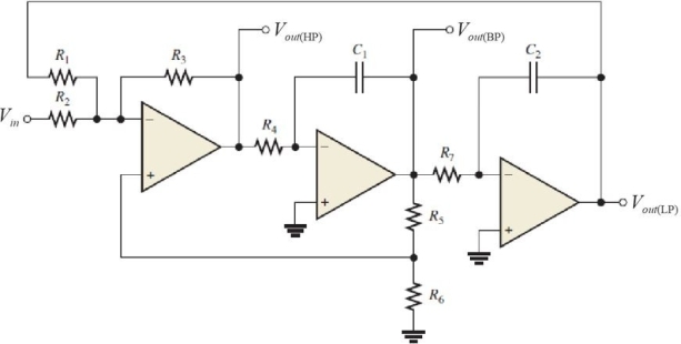 Figure 3
Refer to Figure 3. The last stage is
A)a differentiator
B)an inverting amp
C)an integrator
D)a summing amplifier
Question
Question
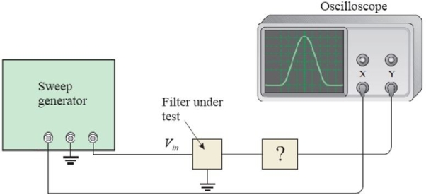 Figure 4 A test of a filter using an oscilloscope
Refer to Figure 4. The oscilloscope needs to
A)generate an internal time base
B)use normal triggering
C)use external triggering
D)be in X- Y mode
Question
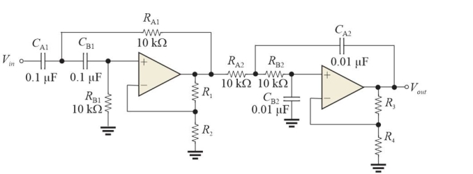 Figure 2 Note that the capacitors have different values.
Refer to Figure 2. The circuit is a
A)high- pass filter
B)low- pass filter
C)notch filter
D)bandpass filter
Question
Question
Question
 Figure 2 Note that the capacitors have different values.
Refer to Figure 2. Assume section 1 and section 2 are exchanged. This will
A)change the overall response
B)change the type of filter
C)both A and B
D)neither A nor B
Question
Question
Figure 2 Note that the capacitors have different values.Refer to Figure 2. The fc for the second section is
A)1.6 kHz
B)800 Hz
C)80 Hz
D)160 Hz
Question
Question
Question

Unlock Deck
Sign up to unlock the cards in this deck!
Unlock Deck
Unlock Deck
1/35
Play
Full screen (f)
Deck 15: Active Filters
1
Figure 4 A test of a filter using an oscilloscopeRefer to Figure 4. The signal on the X channel of the oscilloscope is a(n)
A)sawtooth
B)continuous frequency sinusoidal wave
C)amplitude modulated frequency
D)constant amplitude swept frequency
A
2
The critical frequency of a high- pass filter is where the response is
A)-20 dB from the passband response
B)at its highest point
C)-3 dB from the passband response
D)-6 dB from the passband response
A)-20 dB from the passband response
B)at its highest point
C)-3 dB from the passband response
D)-6 dB from the passband response
C
3
A high Q bandpass filter
A)can reject a specific frequency
B)has a narrow bandwidth
C)is usually constructed from cascaded low- pass and high- pass filters
D)all of the above
A)can reject a specific frequency
B)has a narrow bandwidth
C)is usually constructed from cascaded low- pass and high- pass filters
D)all of the above
B
4
Figure 1 Stage 1: DF = 1.848 and R1/R2 = 0.152; stage 2: DF = 0.765 and R3/R4 =1.235.Refer to Figure 1 with values as given. R3 should have a value of
A)1.8 k▲
B)1.5 k▲
C)1.2 k▲
D)none of the above
Unlock Deck
Unlock for access to all 35 flashcards in this deck.
Unlock Deck
k this deck
5
The biquad filter has
A)a summing amplifier, an inverting amplifier, and an integrator
B)an inverting amplifier and two differentiators
C)a summing amplifier and two differentiators
D)an inverting amplifier and two integrators
A)a summing amplifier, an inverting amplifier, and an integrator
B)an inverting amplifier and two differentiators
C)a summing amplifier and two differentiators
D)an inverting amplifier and two integrators
Unlock Deck
Unlock for access to all 35 flashcards in this deck.
Unlock Deck
k this deck
6
Figure 1 Stage 1: DF = 1.848 and R1/R2 = 0.152; stage 2: DF = 0.765 and R3/R4 =1.235.Refer to Figure 1 with values as given. R1 should have a value of
A)1.2 k▲
B)1.8 k▲
C)1.5 k▲
D)none of the above
Unlock Deck
Unlock for access to all 35 flashcards in this deck.
Unlock Deck
k this deck
7
Figure 5 Response curve for three different filtersRefer to Figure 5. The response labeled "A" represents a
A)Butterworth response
B)Bessel response
C)Chebyshev response
D)none of the above
Unlock Deck
Unlock for access to all 35 flashcards in this deck.
Unlock Deck
k this deck
8
A low- pass filter has a critical frequency of 10 kHz. The bandpass is
A)20 kHz
B)5.0 kHz
C)15 kHz
D)10 kHz
A)20 kHz
B)5.0 kHz
C)15 kHz
D)10 kHz
Unlock Deck
Unlock for access to all 35 flashcards in this deck.
Unlock Deck
k this deck
9
Figure 5 Response curve for three different filtersRefer to Figure 5. The response labeled "B" represents a
A)Butterworth response
B)Bessel response
C)Chebyshev response
D)none of the above
Unlock Deck
Unlock for access to all 35 flashcards in this deck.
Unlock Deck
k this deck
10
Figure 2 Note that the capacitors have different values.Refer to Figure 2. The fc for the first section is
A)800 Hz
B)160 Hz
C)80 Hz
D)1.6 kHz
Unlock Deck
Unlock for access to all 35 flashcards in this deck.
Unlock Deck
k this deck
11
Figure 3Refer to Figure 3. This type of filter is called a
A)biquad filter
B)Sallen- Key filter
C)multiple- feedback filter
D)state- variable filter
Unlock Deck
Unlock for access to all 35 flashcards in this deck.
Unlock Deck
k this deck
12
The bandwidth of a bandpass filter is measured at
A)the -2 dB frequencies
B)the -6 dB frequencies
C)the -4 dB frequencies
D)none of the above
A)the -2 dB frequencies
B)the -6 dB frequencies
C)the -4 dB frequencies
D)none of the above
Unlock Deck
Unlock for access to all 35 flashcards in this deck.
Unlock Deck
k this deck
13
The best response to use for pulses is
A)Butterworth response
B)Bessel response
C)Chebyshev response
D)none of the above
A)Butterworth response
B)Bessel response
C)Chebyshev response
D)none of the above
Unlock Deck
Unlock for access to all 35 flashcards in this deck.
Unlock Deck
k this deck
14
A basic one- pole RC low- pass filter has fc = 5.9 kHz using a 0.01 µF capacitor. The resistor value is
A)2.7 k▲
B)1.6 k▲
C)16 k▲
D)270 ▲
A)2.7 k▲
B)1.6 k▲
C)16 k▲
D)270 ▲
Unlock Deck
Unlock for access to all 35 flashcards in this deck.
Unlock Deck
k this deck
15
Figure 1 Stage 1: DF = 1.848 and R1/R2 = 0.152; stage 2: DF = 0.765 and R3/R4 =1.235.Refer to Figure 1. Assume Vin = 1.0 Vpp sine wave at 20 kHz. At this frequency, Vout is approximately
A)1.0 Vpp
B)10 mVpp
C)1.0 mVpp
D)100 µVpp
Unlock Deck
Unlock for access to all 35 flashcards in this deck.
Unlock Deck
k this deck
16
Figure 2 Note that the capacitors have different values.Refer to Figure 2. Assume the capacitors in section 1 are made larger. This change will
A)decrease the bandwidth
B)increase the bandwidth
C)not affect the bandwidth
Unlock Deck
Unlock for access to all 35 flashcards in this deck.
Unlock Deck
k this deck
17
Figure 4 A test of a filter using an oscilloscopeRefer to Figure 4. The block with the ? on it represents a
A)low- pass filter
B)impedance matching circuit
C)detector
D)amplifier
Unlock Deck
Unlock for access to all 35 flashcards in this deck.
Unlock Deck
k this deck
18
Figure 3Refer to Figure 3. An advantage of this type of filter is that it
A)the low and high- pass outputs are equivalent to a 4- pole filter
B)can be optimized for all three outputs
C)the bandpass output can have a very high Q
D)all of the above
Unlock Deck
Unlock for access to all 35 flashcards in this deck.
Unlock Deck
k this deck
19
Assume a high- pass filter and a low- pass filter are cascaded to form a band- pass filter. The upper cutoff frequency will be determined by
A)the high- pass filter
B)answer depends on the order of the filters
C)the low- pass filter
D)none of the above
A)the high- pass filter
B)answer depends on the order of the filters
C)the low- pass filter
D)none of the above
Unlock Deck
Unlock for access to all 35 flashcards in this deck.
Unlock Deck
k this deck
20
Figure 4 A test of a filter using an oscilloscopeRefer to Figure 4. The input signal to the filter (Vin)is a(n)
A)continuous frequency sinusoidal wave
B)amplitude modulated frequency
C)constant amplitude swept frequency
D)sawtooth
Unlock Deck
Unlock for access to all 35 flashcards in this deck.
Unlock Deck
k this deck
21
Figure 1 Stage 1: DF = 1.848 and R1/R2 = 0.152; stage 2: DF = 0.765 and R3/R4 =1.235.Refer to Figure 1. The type of filter is a
A)low- pass Sallen- Key filter
B)high- pass Sallen- Key filter
C)low- pass biquad filter
D)high- pass biquad filter
Unlock Deck
Unlock for access to all 35 flashcards in this deck.
Unlock Deck
k this deck
22
Figure 1 Stage 1: DF = 1.848 and R1/R2 = 0.152; stage 2: DF = 0.765 and R3/R4 =1.235.Refer to Figure 1. The ideal roll- off rate is
A)-120 dB/decade
B)-80 dB/decade
C)-40 dB/decade
D)-20 dB/decade
Unlock Deck
Unlock for access to all 35 flashcards in this deck.
Unlock Deck
k this deck
23
The damping factor, DF, is determined by the number of poles in a filter.
Unlock Deck
Unlock for access to all 35 flashcards in this deck.
Unlock Deck
k this deck
24
Figure 3Refer to Figure 3. The last stage is
A)a differentiator
B)an inverting amp
C)an integrator
D)a summing amplifier
Unlock Deck
Unlock for access to all 35 flashcards in this deck.
Unlock Deck
k this deck
25
A basic RC (one R, oneC)filter has a -20dB/decade roll- off.
Unlock Deck
Unlock for access to all 35 flashcards in this deck.
Unlock Deck
k this deck
26
Figure 4 A test of a filter using an oscilloscopeRefer to Figure 4. The oscilloscope needs to
A)generate an internal time base
B)use normal triggering
C)use external triggering
D)be in X- Y mode
Unlock Deck
Unlock for access to all 35 flashcards in this deck.
Unlock Deck
k this deck
27
Figure 2 Note that the capacitors have different values.Refer to Figure 2. The circuit is a
A)high- pass filter
B)low- pass filter
C)notch filter
D)bandpass filter
Unlock Deck
Unlock for access to all 35 flashcards in this deck.
Unlock Deck
k this deck
28
A single- pole filter cannot be used as a notch filter.
Unlock Deck
Unlock for access to all 35 flashcards in this deck.
Unlock Deck
k this deck
29
The Q of a band- pass filter is inversely proportional to the damping factor.
Unlock Deck
Unlock for access to all 35 flashcards in this deck.
Unlock Deck
k this deck
30
Figure 2 Note that the capacitors have different values.Refer to Figure 2. Assume section 1 and section 2 are exchanged. This will
A)change the overall response
B)change the type of filter
C)both A and B
D)neither A nor B
Unlock Deck
Unlock for access to all 35 flashcards in this deck.
Unlock Deck
k this deck
31
The Chebyshev filter is noted for its flat response in the passband.
Unlock Deck
Unlock for access to all 35 flashcards in this deck.
Unlock Deck
k this deck
32
Figure 2 Note that the capacitors have different values.Refer to Figure 2. The fc for the second section is
A)1.6 kHz
B)800 Hz
C)80 Hz
D)160 Hz
Unlock Deck
Unlock for access to all 35 flashcards in this deck.
Unlock Deck
k this deck
33
A biquad filter has both low- pass and high- pass outputs.
Unlock Deck
Unlock for access to all 35 flashcards in this deck.
Unlock Deck
k this deck
34
The damping factor, DF, affects an active filter's response characteristics.
Unlock Deck
Unlock for access to all 35 flashcards in this deck.
Unlock Deck
k this deck
35
The bandwidth of a basic band- pass filter is measured between the center frequency and a critical frequency.
Unlock Deck
Unlock for access to all 35 flashcards in this deck.
Unlock Deck
k this deck
Unlock Deck
Unlock for access to all 35 flashcards in this deck.


