Deck 16: Rl Circuits
Full screen (f)
Question
Given the circuit in Figure 16-3, what is the voltage rms) across the inductor?
A) 4 V
B) 7.07 V
C) 10 V
D) 6 V
Question
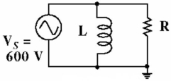
In the circuit in Figure 16-1, assume that XL, = R. The phase angle is 45°.
Question
Question
In the circuit in Figure 16-1, increasing the frequency will cause an increase in circuit current.
Question
Given the circuit in Figure 16-3, what is the voltage rms) across the resistor?
A) 4 V
B) 7.07 V
C) 3 V
D) 8 V
Question
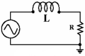
In the circuit in Figure 16-2, the current through the inductor equals the current through the resistor.
Question
Question
In the circuit in Figure 16-1, increasing the frequency will cause an increase in circuit impedance.
Question
Question
Given the circuit in Figure , what is the total circuit impedence Z?
A) 2.65 kΩ
B) 7 kΩ
C) 5.0 kΩ
D) 500 Ω
Question
In the circuit in Figure 16-1, The current lags the voltage.
Question
Question
In the circuit in Figure 16-2, increasing the inductance value will cause an increase in circuit current.
Question
Question
Given the circuit in Figure 16-3, what is the total circuit current?
A) 7.07 mA
B) 2.0 mA
C) 20 mA
D) 100 mA
Question
In the circuit in Figure 16-1, increasing the inductance value will cause an increase in circuit current.
Question
In the circuit in Figure 16-2, increasing the frequency will cause an increase in circuit current.
Question
In the circuit in Figure 16-2, assume that XL = R. The phase angle is 45°.
Question
In the circuit in Figure 16-2, increasing the frequency will cause an increase in circuit impedence.
Question
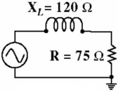
What is the total circuit impedance in Figure ?
A) 141.5 Ω
B) 195 Ω
C) 14.15 Ω
D) 120 Ω
Question
Given the circuit in Figure , what is the total circuit impedance?
A) 44.96 Ω
B) 449.6 Ω
C) 222.6 Ω
D) 268.3 Ω
Question
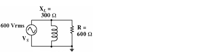
Given the circuit in Figure 16-5, what is the current through the inductor?
A) 1.0 A
B) 2.0 A
C) 3.0 A
D) 0.707 A
Question
Question
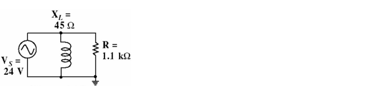
Given the circuit in Figure 16-6, what is the current through the resistor?
A) 21.8 mA
B) 1100 mA
C) 45.3 mA
D) 207.5 mA
Question
Given the circuit in Figure 16-6, what is the current through the inductor?
A) 533.3 mA
B) 300 mA
C) 21.8 mA
D) 218 mA
Question
Given the circuit in Figure 16-6, what is the impedance phase angle?
A) 87.6°
B) 45°
C) 23.4°
D) 43.2°
Question
Given the circuit in Figure 16-6, does the total current lead or lag the total voltage?
A) The total current IT) lags the total voltage VS).
B) The total current IT) leads the total voltage VS).
Question
Question
Given the circuit in Figure 16-5, what is the total circuit current?
A) 5 A
B) 3 A
C) 4.69 mA
D) 2.24 A
Question
Question
Question
Given the circuit in Figure , what is the total circuit impedance?
A) 569 Ω
B) 26.8 Ω
C) 268 Ω
D) 22.6 Ω
Question
Given the circuit in Figure 16-5, what is the current through the resistor?
A) 3.0 A
B) 0.707 A
C) 2.0 A
D) 1.0 A
Question
Question
Question
What is the Impedance of the circuit in Figure , expressed in polar form?
A) 120 32° Ω
32° Ω
B) 120 11ec81bf_ec6d_acdc_bc38_29a3f7414e20_TB34225555_11 -58° Ω
C) 141.5 11ec81bf_ec6d_acdc_bc38_29a3f7414e20_TB34225555_11 -58° Ω
D) 141.5 11ec81bf_ec6d_acdc_bc38_29a3f7414e20_TB34225555_11 58° Ω
A) 120
32° ΩB) 120 11ec81bf_ec6d_acdc_bc38_29a3f7414e20_TB34225555_11 -58° Ω
C) 141.5 11ec81bf_ec6d_acdc_bc38_29a3f7414e20_TB34225555_11 -58° Ω
D) 141.5 11ec81bf_ec6d_acdc_bc38_29a3f7414e20_TB34225555_11 58° Ω
Question
Question
Question
Given the circuit in Figure 16-6, what is the total circuit current?
A) 57.7 mA
B) 555.1 mA
C) 4.69 mA
D) 533.8 mA
Question
Question
Question
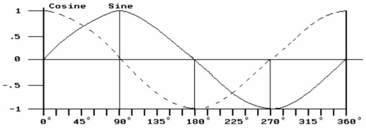 Figure 16-7
In Figure 16-7, the plot of the sine wave could represent the and the cosine wave could represent the
Relationship in a purely inductive circuit
A) current, voltage
B) current, impedance
C) voltage, current
D) voltage, impedance
Question
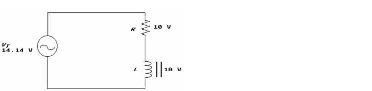 Figure 16-8
In Figure 16-8, for the voltage across the resistor to equal the voltage across the inductor:
A) XL must be smaller than R
B) XL must equal R.
C) XL must be larger than R
D) impedance must be zero.
Question
Question
Question
Figure 16-8The inverse of inductive reactance is:
A) impedance
B) resistance
C) inductive susceptance
D) capacitive susceptance
Question

Unlock Deck
Sign up to unlock the cards in this deck!
Unlock Deck
Unlock Deck
1/47
Play
Full screen (f)
Deck 16: Rl Circuits
1
Given the circuit in Figure 16-3, what is the voltage rms) across the inductor?
A) 4 V
B) 7.07 V
C) 10 V
D) 6 V
6 V
2
In the circuit in Figure 16-1, assume that XL, = R. The phase angle is 45°.
True
3
In a series RL circuit, the resultant voltage vector represents the total applied voltage.
True
4
In the circuit in Figure 16-1, increasing the frequency will cause an increase in circuit current.
Unlock Deck
Unlock for access to all 47 flashcards in this deck.
Unlock Deck
k this deck
5
Given the circuit in Figure 16-3, what is the voltage rms) across the resistor?
A) 4 V
B) 7.07 V
C) 3 V
D) 8 V
Unlock Deck
Unlock for access to all 47 flashcards in this deck.
Unlock Deck
k this deck
6
In the circuit in Figure 16-2, the current through the inductor equals the current through the resistor.
Unlock Deck
Unlock for access to all 47 flashcards in this deck.
Unlock Deck
k this deck
7
For parallel ac circuits containing resistance and inductive reactance, total current can only be found using right-triangle methods.
Unlock Deck
Unlock for access to all 47 flashcards in this deck.
Unlock Deck
k this deck
8
In the circuit in Figure 16-1, increasing the frequency will cause an increase in circuit impedance.
Unlock Deck
Unlock for access to all 47 flashcards in this deck.
Unlock Deck
k this deck
9
For series AC circuits containing both resistance and inductive reactance, total opposition to current flow cannot be found by simply adding ohmic values or oppositions to current.
Unlock Deck
Unlock for access to all 47 flashcards in this deck.
Unlock Deck
k this deck
10
Given the circuit in Figure , what is the total circuit impedence Z?
A) 2.65 kΩ
B) 7 kΩ
C) 5.0 kΩ
D) 500 Ω
Unlock Deck
Unlock for access to all 47 flashcards in this deck.
Unlock Deck
k this deck
11
In the circuit in Figure 16-1, The current lags the voltage.
Unlock Deck
Unlock for access to all 47 flashcards in this deck.
Unlock Deck
k this deck
12
Phase angle is the difference in phase between the applied voltage and the circuit current.
Unlock Deck
Unlock for access to all 47 flashcards in this deck.
Unlock Deck
k this deck
13
In the circuit in Figure 16-2, increasing the inductance value will cause an increase in circuit current.
Unlock Deck
Unlock for access to all 47 flashcards in this deck.
Unlock Deck
k this deck
14
For voltage-current vector diagrams relating to series RL circuits, current is the reference vector because it is the same throughout the circuit.
Unlock Deck
Unlock for access to all 47 flashcards in this deck.
Unlock Deck
k this deck
15
Given the circuit in Figure 16-3, what is the total circuit current?
A) 7.07 mA
B) 2.0 mA
C) 20 mA
D) 100 mA
Unlock Deck
Unlock for access to all 47 flashcards in this deck.
Unlock Deck
k this deck
16
In the circuit in Figure 16-1, increasing the inductance value will cause an increase in circuit current.
Unlock Deck
Unlock for access to all 47 flashcards in this deck.
Unlock Deck
k this deck
17
In the circuit in Figure 16-2, increasing the frequency will cause an increase in circuit current.
Unlock Deck
Unlock for access to all 47 flashcards in this deck.
Unlock Deck
k this deck
18
In the circuit in Figure 16-2, assume that XL = R. The phase angle is 45°.
Unlock Deck
Unlock for access to all 47 flashcards in this deck.
Unlock Deck
k this deck
19
In the circuit in Figure 16-2, increasing the frequency will cause an increase in circuit impedence.
Unlock Deck
Unlock for access to all 47 flashcards in this deck.
Unlock Deck
k this deck
20
What is the total circuit impedance in Figure ?
A) 141.5 Ω
B) 195 Ω
C) 14.15 Ω
D) 120 Ω
Unlock Deck
Unlock for access to all 47 flashcards in this deck.
Unlock Deck
k this deck
21
Given the circuit in Figure , what is the total circuit impedance?
A) 44.96 Ω
B) 449.6 Ω
C) 222.6 Ω
D) 268.3 Ω
Unlock Deck
Unlock for access to all 47 flashcards in this deck.
Unlock Deck
k this deck
22
Given the circuit in Figure 16-5, what is the current through the inductor?
A) 1.0 A
B) 2.0 A
C) 3.0 A
D) 0.707 A
Unlock Deck
Unlock for access to all 47 flashcards in this deck.
Unlock Deck
k this deck
23
In a series resistor/inductor circuit:
A) the same current flows through both the resistor and the inductor.
B) the resistor voltage is in phase with the current.
C) the inductor voltage leads the current by 90 degrees.
D) All of the above are correct.
A) the same current flows through both the resistor and the inductor.
B) the resistor voltage is in phase with the current.
C) the inductor voltage leads the current by 90 degrees.
D) All of the above are correct.
Unlock Deck
Unlock for access to all 47 flashcards in this deck.
Unlock Deck
k this deck
24
Given the circuit in Figure 16-6, what is the current through the resistor?
A) 21.8 mA
B) 1100 mA
C) 45.3 mA
D) 207.5 mA
Unlock Deck
Unlock for access to all 47 flashcards in this deck.
Unlock Deck
k this deck
25
Given the circuit in Figure 16-6, what is the current through the inductor?
A) 533.3 mA
B) 300 mA
C) 21.8 mA
D) 218 mA
Unlock Deck
Unlock for access to all 47 flashcards in this deck.
Unlock Deck
k this deck
26
Given the circuit in Figure 16-6, what is the impedance phase angle?
A) 87.6°
B) 45°
C) 23.4°
D) 43.2°
Unlock Deck
Unlock for access to all 47 flashcards in this deck.
Unlock Deck
k this deck
27
Given the circuit in Figure 16-6, does the total current lead or lag the total voltage?
A) The total current IT) lags the total voltage VS).
B) The total current IT) leads the total voltage VS).
Unlock Deck
Unlock for access to all 47 flashcards in this deck.
Unlock Deck
k this deck
28
The impedance of a series resistor/inductor circuit is defined as: 56 Ω + j75 Ω. What is the resistance value?
A) 93.6 Ω
B) 56 Ω
C) 75 Ω
D) 19 Ω
A) 93.6 Ω
B) 56 Ω
C) 75 Ω
D) 19 Ω
Unlock Deck
Unlock for access to all 47 flashcards in this deck.
Unlock Deck
k this deck
29
Given the circuit in Figure 16-5, what is the total circuit current?
A) 5 A
B) 3 A
C) 4.69 mA
D) 2.24 A
Unlock Deck
Unlock for access to all 47 flashcards in this deck.
Unlock Deck
k this deck
30
In a series RL circuit, if resistance increases, impedance will:
A) increase
B) drop to zero
C) decrease
D) remain the same.
A) increase
B) drop to zero
C) decrease
D) remain the same.
Unlock Deck
Unlock for access to all 47 flashcards in this deck.
Unlock Deck
k this deck
31
What is the Impedance of the circuit in Figure , expressed in rectangular form?
A) 75 Ω + j120 Ω
B) 141 Ω + j120 Ω
C) 120 Ω + j75 Ω
D) j75 Ω + j120 Ω
A) 75 Ω + j120 Ω
B) 141 Ω + j120 Ω
C) 120 Ω + j75 Ω
D) j75 Ω + j120 Ω
Unlock Deck
Unlock for access to all 47 flashcards in this deck.
Unlock Deck
k this deck
32
Given the circuit in Figure , what is the total circuit impedance?
A) 569 Ω
B) 26.8 Ω
C) 268 Ω
D) 22.6 Ω
Unlock Deck
Unlock for access to all 47 flashcards in this deck.
Unlock Deck
k this deck
33
Given the circuit in Figure 16-5, what is the current through the resistor?
A) 3.0 A
B) 0.707 A
C) 2.0 A
D) 1.0 A
Unlock Deck
Unlock for access to all 47 flashcards in this deck.
Unlock Deck
k this deck
34
A 12 mH inductor is used in a circuit with a 10 kHz source. What is the inductive reactance?
A) 500 ohms
B) 754 ohms
C) 127 ohms
D) 1.33 k ohms
A) 500 ohms
B) 754 ohms
C) 127 ohms
D) 1.33 k ohms
Unlock Deck
Unlock for access to all 47 flashcards in this deck.
Unlock Deck
k this deck
35
If XL = 100 ohms and R = 100 ohms in a series RL circuit, then impedance will be:
A) 200 Ω
B) 14.14 Ω
C) 100 Ω
D) 141.4 Ω
A) 200 Ω
B) 14.14 Ω
C) 100 Ω
D) 141.4 Ω
Unlock Deck
Unlock for access to all 47 flashcards in this deck.
Unlock Deck
k this deck
36
What is the Impedance of the circuit in Figure , expressed in polar form?
A) 120 32° Ω
B) 120 11ec81bf_ec6d_acdc_bc38_29a3f7414e20_TB34225555_11 -58° Ω
C) 141.5 11ec81bf_ec6d_acdc_bc38_29a3f7414e20_TB34225555_11 -58° Ω
D) 141.5 11ec81bf_ec6d_acdc_bc38_29a3f7414e20_TB34225555_11 58° Ω
A) 120
32° ΩB) 120 11ec81bf_ec6d_acdc_bc38_29a3f7414e20_TB34225555_11 -58° Ω
C) 141.5 11ec81bf_ec6d_acdc_bc38_29a3f7414e20_TB34225555_11 -58° Ω
D) 141.5 11ec81bf_ec6d_acdc_bc38_29a3f7414e20_TB34225555_11 58° Ω
Unlock Deck
Unlock for access to all 47 flashcards in this deck.
Unlock Deck
k this deck
37
What is the phase angle of the circuit in Figure 16-4?
A) 32°
B) -32°
C) 58°
D) -58°
A) 32°
B) -32°
C) 58°
D) -58°
Unlock Deck
Unlock for access to all 47 flashcards in this deck.
Unlock Deck
k this deck
38
A circuit has an apparent power of 240 VA, and a power factor of 0.943. What is the true power dissipated by the circuit?
A) 13.6 W
B) 226 W
C) 84.5 W
D) 240 W
A) 13.6 W
B) 226 W
C) 84.5 W
D) 240 W
Unlock Deck
Unlock for access to all 47 flashcards in this deck.
Unlock Deck
k this deck
39
Given the circuit in Figure 16-6, what is the total circuit current?
A) 57.7 mA
B) 555.1 mA
C) 4.69 mA
D) 533.8 mA
Unlock Deck
Unlock for access to all 47 flashcards in this deck.
Unlock Deck
k this deck
40
In a series RL circuit where R = 100 Ω and XL = 50 Ω, which of the following combinations is equivalent to the given series circuit?
A) R = 40 Ω in parallel with XL = 20 Ω
B) R = 125 Ω in parallel with XL = 250 Ω
C) R = 250 Ω in parallel with XL = 125 Ω
D) R = 20 Ω in parallel with XL = 40 Ω
A) R = 40 Ω in parallel with XL = 20 Ω
B) R = 125 Ω in parallel with XL = 250 Ω
C) R = 250 Ω in parallel with XL = 125 Ω
D) R = 20 Ω in parallel with XL = 40 Ω
Unlock Deck
Unlock for access to all 47 flashcards in this deck.
Unlock Deck
k this deck
41
The total opposition that a series or parallel RL circuit offers to current flow is called .
A) inductive impedance
B) susceptance
C) reactance
D) impedance
A) inductive impedance
B) susceptance
C) reactance
D) impedance
Unlock Deck
Unlock for access to all 47 flashcards in this deck.
Unlock Deck
k this deck
42
Figure 16-7In Figure 16-7, the plot of the sine wave could represent the and the cosine wave could represent the
Relationship in a purely inductive circuit
A) current, voltage
B) current, impedance
C) voltage, current
D) voltage, impedance
Unlock Deck
Unlock for access to all 47 flashcards in this deck.
Unlock Deck
k this deck
43
Figure 16-8In Figure 16-8, for the voltage across the resistor to equal the voltage across the inductor:
A) XL must be smaller than R
B) XL must equal R.
C) XL must be larger than R
D) impedance must be zero.
Unlock Deck
Unlock for access to all 47 flashcards in this deck.
Unlock Deck
k this deck
44
Switching power supplies:
A) are efficient at converting ac to dc
B) contain pulse-width modulators
C) can change unregulated dc to high frequency pulses
D) all of the above
A) are efficient at converting ac to dc
B) contain pulse-width modulators
C) can change unregulated dc to high frequency pulses
D) all of the above
Unlock Deck
Unlock for access to all 47 flashcards in this deck.
Unlock Deck
k this deck
45
Resistance and inductive reactance must be added in a series RL circuit.
A) using vectors, or Pythagorean Theorem
B) inductively
C) using Kirchhoff's Voltage Law
D) both A and C
A) using vectors, or Pythagorean Theorem
B) inductively
C) using Kirchhoff's Voltage Law
D) both A and C
Unlock Deck
Unlock for access to all 47 flashcards in this deck.
Unlock Deck
k this deck
46
Figure 16-8The inverse of inductive reactance is:
A) impedance
B) resistance
C) inductive susceptance
D) capacitive susceptance
Unlock Deck
Unlock for access to all 47 flashcards in this deck.
Unlock Deck
k this deck
47
In a series RL circuit where R = 100 Ω and XL = 50 Ω. What is the total impedance of this circuit?
A) 111.8
26.6°
B) 111.8
-26.6°
C) 111.8
-63.4°
D) 111.8
63.4°
A) 111.8
26.6°
B) 111.8
-26.6°
C) 111.8
-63.4°
D) 111.8
63.4°
Unlock Deck
Unlock for access to all 47 flashcards in this deck.
Unlock Deck
k this deck
Unlock Deck
Unlock for access to all 47 flashcards in this deck.


