Deck 18: Passive Filters
Full screen (f)
Question
Question
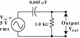 Figure 18-1
The capacitive reactance in Figure 18-1 is equal to the resistance at the critical frequency.
Question
Question
Question
Question
Question
Question
Question
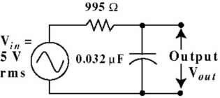 Figure 18-3
The filter in Figure 18-3 has a Roll-off of:
A) -3 dB per decade
B) -20 dB per decade
C) -40 dB per decade
D) -6 dB per decade
Question
Question
Question
Question
Question
Question
Question
Figure 18-1Given a frequency of 440 Hz, one Decade higher would be a frequency of:
A) 4 kHz
B) 220 Hz
C) 880 Hz
D) 4,400 Hz
Question
 Figure 18-1
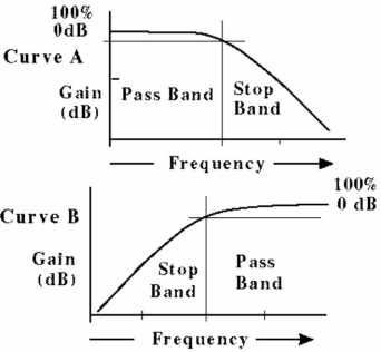 Figure 18-2
Which of the two response curves in Figure 18-2 A or B) represents the response of the circuit in Figure 18-1?
A) Curve A
B) Curve B
Question
Figure 18-3The capacitive reactance in Figure 18-3 is equal to the resistance at the critical frequency.
Question
Figure 18-3The circuit in Figure 18-3 is:
A) a high-pass filter
B) a band-stop filter
C) a low-pass filter
D) a band-pass filter
Question
Figure 18-3The circuit in Figure 18-3 has a critical frequency of:
A) 318.3 kHz
B) 13.18 kHz
C) 5.0 kHz
D) 50.0 kHz
Question
Question
Question
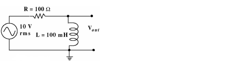 Figure 18-5
The filter in Figure 18-5 has a Roll-off of:
A) -40 dB per decade
B) -3 dB per decade
C) -6 dB per decade
D) -20 dB per decade
Question
Question
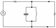 Figure 18-9
Identify the filter circuit in Figure 18-9 above.
A) High Pass
B) Band Pass
C) Band Stop
D) Low Pass
Question
Question
Question
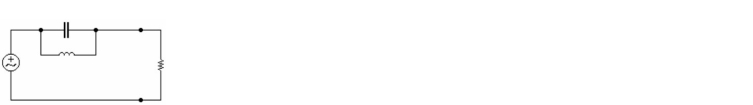 Figure 18-6
Identify the filter circuit in Figure 18-6 above.
A) Band Stop
B) Low Pass
C) Band Pass
D) High Pass
Question
In a low-pass RC filter, having a cutoff frequency of 2 kHz, C = 80nF. Determine R.
A) 98.0 Ω
B) 44.7 Ω
C) 995 Ω
D) 22.7 Ω
Question
Identify the filter circuit in Figure 18-10 above.
A) Low Pass
B) High Pass
C) Band Stop
D) Band Pass
Question
Decibels are used to provide a _ between voltage levels.
A) comparison
B) common level
C) value
D) reference
Question
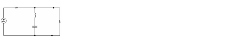
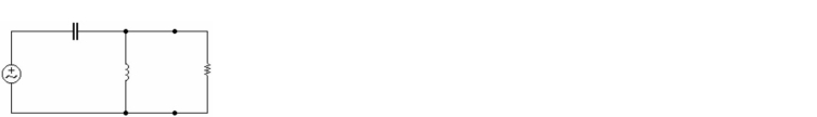 Figure 18-7
Identify the filter circuit in Figure 18-7 above.
A) Band Stop
B) Low Pass
C) High Pass
D) Band Pass
Question
A high-pass RC filter can be changed to a low-pass RC filter by _ .
A) adding another capacitor
B) reversing the position of the resistor and capacitor
C) adding another resistor
D) adding both another resistor and capacitor
Question
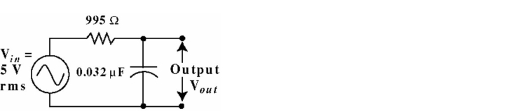 Figure 18-3
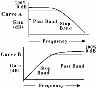 Figure 18-4
The frequency at which the output voltage of a filter is 70.7% of the input voltage is called the:
A) half-power point
B) critical frequency
C) break frequency
D) all of the above
Question
Question
Figure 18-3 Figure 18-4Which of the two response curves in Figure 18-4 A or B) represents the response of the circuit in Figure 18-3?
A) Curve A
B) Curve B
Question
Figure 18-5The circuit in Figure 18-5 is:
A) a low-pass filter
B) a high-pass filter
C) a band-pass filter
D) a notch filter
Question
Question
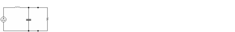 Figure 18-8
Identify the filter circuit in Figure 18-8 above.
A) Low Pass
B) Band Pass
C) High Pass
D) Band Stop
Question
The bandwidth of a resonant circuit is determined by two points on the curve known as .
A) the half power points
B) fcutoff
C) Q Point
D) both A and B
Question
A low-pass filter and a high-pass filter in parallel with each other, would form a _ filter.
A) band-stop
B) band-pass
C) all-pass
D) both A and B
E) none of the above

Unlock Deck
Sign up to unlock the cards in this deck!
Unlock Deck
Unlock Deck
1/41
Play
Full screen (f)
Deck 18: Passive Filters
1
The range of low frequencies passed by a low-pass filter within a specified limit is called the stopband.
False
2
Figure 18-1The capacitive reactance in Figure 18-1 is equal to the resistance at the critical frequency.
True
3
The output voltage, in Figure 18-1 is how many dB down from the input voltage, at the critical frequency?
A) -0.707 dB
B) -20 dB
C) -3 dB
D) 0 dB
A) -0.707 dB
B) -20 dB
C) -3 dB
D) 0 dB
-3 dB
4
The circuit in Figure 18-1 is:
A) a low-pass filter
B) a band-stop filter
C) a high-pass filter
D) a band-pass filter
A) a low-pass filter
B) a band-stop filter
C) a high-pass filter
D) a band-pass filter
Unlock Deck
Unlock for access to all 41 flashcards in this deck.
Unlock Deck
k this deck
5
The circuit in Figure 18-1 has a critical frequency of:
A) 3.18 kHz
B) 31.8 kHz
C) 3.18 MHz
D) 318 kHz
A) 3.18 kHz
B) 31.8 kHz
C) 3.18 MHz
D) 318 kHz
Unlock Deck
Unlock for access to all 41 flashcards in this deck.
Unlock Deck
k this deck
6
What is the output voltage, in Figure 18-3 at a frequency of 1.0 kHz?
A) 0.269 V
B) 4.90 V
C) 1.76 V
D) 3.45 V
A) 0.269 V
B) 4.90 V
C) 1.76 V
D) 3.45 V
Unlock Deck
Unlock for access to all 41 flashcards in this deck.
Unlock Deck
k this deck
7
The phase shift of the circuit in Figure 18-1, at the critical frequency is:
A) 45°
B) 90°
C) 0°
D) 60.254°
A) 45°
B) 90°
C) 0°
D) 60.254°
Unlock Deck
Unlock for access to all 41 flashcards in this deck.
Unlock Deck
k this deck
8
Frequency response is a graph of voltage gain versus frequency.
Unlock Deck
Unlock for access to all 41 flashcards in this deck.
Unlock Deck
k this deck
9
Figure 18-3The filter in Figure 18-3 has a Roll-off of:
A) -3 dB per decade
B) -20 dB per decade
C) -40 dB per decade
D) -6 dB per decade
Unlock Deck
Unlock for access to all 41 flashcards in this deck.
Unlock Deck
k this deck
10
At the cutoff frequency, the voltage gain is 63.6% of the maximum.
Unlock Deck
Unlock for access to all 41 flashcards in this deck.
Unlock Deck
k this deck
11
What is the output voltage, in Figure 18-1 at a frequency of 50 kHz?
A) 3.17 V
B) 1.76 V
C) 4.22 V
D) 3.45 V
A) 3.17 V
B) 1.76 V
C) 4.22 V
D) 3.45 V
Unlock Deck
Unlock for access to all 41 flashcards in this deck.
Unlock Deck
k this deck
12
The phase shift of the circuit in Figure 18-3, at the critical frequency is:
A) -90°
B) 0°
C) 60.254°
D) -45°
A) -90°
B) 0°
C) 60.254°
D) -45°
Unlock Deck
Unlock for access to all 41 flashcards in this deck.
Unlock Deck
k this deck
13
The filter in Figure 18-1 has a Roll-off of:
A) -40 dB per decade
B) -3 dB per decade
C) -20 dB per decade
D) -6 dB per decade
A) -40 dB per decade
B) -3 dB per decade
C) -20 dB per decade
D) -6 dB per decade
Unlock Deck
Unlock for access to all 41 flashcards in this deck.
Unlock Deck
k this deck
14
The effectiveness of a filter in rejecting signals beyond cutoff frequency is a function of the filter roll-off rating.
Unlock Deck
Unlock for access to all 41 flashcards in this deck.
Unlock Deck
k this deck
15
What is the output voltage, in Figure 18-1 at a frequency of 10 kHz?
A) 4.23 V
B) 5 V
C) 4.77 V
D) 1.50 V
A) 4.23 V
B) 5 V
C) 4.77 V
D) 1.50 V
Unlock Deck
Unlock for access to all 41 flashcards in this deck.
Unlock Deck
k this deck
16
Figure 18-1Given a frequency of 440 Hz, one Decade higher would be a frequency of:
A) 4 kHz
B) 220 Hz
C) 880 Hz
D) 4,400 Hz
Unlock Deck
Unlock for access to all 41 flashcards in this deck.
Unlock Deck
k this deck
17
Figure 18-1 Figure 18-2Which of the two response curves in Figure 18-2 A or B) represents the response of the circuit in Figure 18-1?
A) Curve A
B) Curve B
Unlock Deck
Unlock for access to all 41 flashcards in this deck.
Unlock Deck
k this deck
18
Figure 18-3The capacitive reactance in Figure 18-3 is equal to the resistance at the critical frequency.
Unlock Deck
Unlock for access to all 41 flashcards in this deck.
Unlock Deck
k this deck
19
Figure 18-3The circuit in Figure 18-3 is:
A) a high-pass filter
B) a band-stop filter
C) a low-pass filter
D) a band-pass filter
Unlock Deck
Unlock for access to all 41 flashcards in this deck.
Unlock Deck
k this deck
20
Figure 18-3The circuit in Figure 18-3 has a critical frequency of:
A) 318.3 kHz
B) 13.18 kHz
C) 5.0 kHz
D) 50.0 kHz
Unlock Deck
Unlock for access to all 41 flashcards in this deck.
Unlock Deck
k this deck
21
The output voltage, in Figure 18-3 is how many dB down from the input voltage, at the critical frequency?
A) -20 dB
B) -0.707 dB
C) 0 dB
D) -3 dB
A) -20 dB
B) -0.707 dB
C) 0 dB
D) -3 dB
Unlock Deck
Unlock for access to all 41 flashcards in this deck.
Unlock Deck
k this deck
22
The is defined as the difference between the high and low cut-off frequencies.
A) Q frequency range
B) bandwidth
C) roll-off
D) filter width
A) Q frequency range
B) bandwidth
C) roll-off
D) filter width
Unlock Deck
Unlock for access to all 41 flashcards in this deck.
Unlock Deck
k this deck
23
Figure 18-5The filter in Figure 18-5 has a Roll-off of:
A) -40 dB per decade
B) -3 dB per decade
C) -6 dB per decade
D) -20 dB per decade
Unlock Deck
Unlock for access to all 41 flashcards in this deck.
Unlock Deck
k this deck
24
Which of the following equations is correct for calculating the critical or cut-off frequency for the circuit in Figure 18-5?
A) Fc = 1/2n LR)
B) Fc = 1/[2n L/R)]
C) Fc = 1/[2n LR)]
D) Fc = 2nL/R)
A) Fc = 1/2n LR)
B) Fc = 1/[2n L/R)]
C) Fc = 1/[2n LR)]
D) Fc = 2nL/R)
Unlock Deck
Unlock for access to all 41 flashcards in this deck.
Unlock Deck
k this deck
25
Figure 18-9Identify the filter circuit in Figure 18-9 above.
A) High Pass
B) Band Pass
C) Band Stop
D) Low Pass
Unlock Deck
Unlock for access to all 41 flashcards in this deck.
Unlock Deck
k this deck
26
The output voltage of the circuit in Figure 18-5, at the cut-off critical) frequency is:
A) 7.07 V
B) 0.707 V
C) 4.9 V
D) 1.59 V
A) 7.07 V
B) 0.707 V
C) 4.9 V
D) 1.59 V
Unlock Deck
Unlock for access to all 41 flashcards in this deck.
Unlock Deck
k this deck
27
The term "attenuation" refers to a:
A) phase shift
B) loss or reduction of signal strength
C) signal gain
D) unity gain
A) phase shift
B) loss or reduction of signal strength
C) signal gain
D) unity gain
Unlock Deck
Unlock for access to all 41 flashcards in this deck.
Unlock Deck
k this deck
28
Figure 18-6Identify the filter circuit in Figure 18-6 above.
A) Band Stop
B) Low Pass
C) Band Pass
D) High Pass
Unlock Deck
Unlock for access to all 41 flashcards in this deck.
Unlock Deck
k this deck
29
In a low-pass RC filter, having a cutoff frequency of 2 kHz, C = 80nF. Determine R.
A) 98.0 Ω
B) 44.7 Ω
C) 995 Ω
D) 22.7 Ω
Unlock Deck
Unlock for access to all 41 flashcards in this deck.
Unlock Deck
k this deck
30
Identify the filter circuit in Figure 18-10 above.
A) Low Pass
B) High Pass
C) Band Stop
D) Band Pass
Unlock Deck
Unlock for access to all 41 flashcards in this deck.
Unlock Deck
k this deck
31
Decibels are used to provide a _ between voltage levels.
A) comparison
B) common level
C) value
D) reference
Unlock Deck
Unlock for access to all 41 flashcards in this deck.
Unlock Deck
k this deck
32
Figure 18-7Identify the filter circuit in Figure 18-7 above.
A) Band Stop
B) Low Pass
C) High Pass
D) Band Pass
Unlock Deck
Unlock for access to all 41 flashcards in this deck.
Unlock Deck
k this deck
33
A high-pass RC filter can be changed to a low-pass RC filter by _ .
A) adding another capacitor
B) reversing the position of the resistor and capacitor
C) adding another resistor
D) adding both another resistor and capacitor
Unlock Deck
Unlock for access to all 41 flashcards in this deck.
Unlock Deck
k this deck
34
Figure 18-3 Figure 18-4The frequency at which the output voltage of a filter is 70.7% of the input voltage is called the:
A) half-power point
B) critical frequency
C) break frequency
D) all of the above
Unlock Deck
Unlock for access to all 41 flashcards in this deck.
Unlock Deck
k this deck
35
The critical frequency of the circuit in Figure 18-5 is:
A) 1.59 kHz
B) 135 Hz
C) 159 Hz
D) 60 Hz
A) 1.59 kHz
B) 135 Hz
C) 159 Hz
D) 60 Hz
Unlock Deck
Unlock for access to all 41 flashcards in this deck.
Unlock Deck
k this deck
36
Figure 18-3 Figure 18-4Which of the two response curves in Figure 18-4 A or B) represents the response of the circuit in Figure 18-3?
A) Curve A
B) Curve B
Unlock Deck
Unlock for access to all 41 flashcards in this deck.
Unlock Deck
k this deck
37
Figure 18-5The circuit in Figure 18-5 is:
A) a low-pass filter
B) a high-pass filter
C) a band-pass filter
D) a notch filter
Unlock Deck
Unlock for access to all 41 flashcards in this deck.
Unlock Deck
k this deck
38
What is the output voltage, in Figure 18-3 at a frequency of 20 kHz?
A) 5 V
B) 1.21 V
C) 0.5 V
D) 4.77 V
A) 5 V
B) 1.21 V
C) 0.5 V
D) 4.77 V
Unlock Deck
Unlock for access to all 41 flashcards in this deck.
Unlock Deck
k this deck
39
Figure 18-8Identify the filter circuit in Figure 18-8 above.
A) Low Pass
B) Band Pass
C) High Pass
D) Band Stop
Unlock Deck
Unlock for access to all 41 flashcards in this deck.
Unlock Deck
k this deck
40
The bandwidth of a resonant circuit is determined by two points on the curve known as .
A) the half power points
B) fcutoff
C) Q Point
D) both A and B
Unlock Deck
Unlock for access to all 41 flashcards in this deck.
Unlock Deck
k this deck
41
A low-pass filter and a high-pass filter in parallel with each other, would form a _ filter.
A) band-stop
B) band-pass
C) all-pass
D) both A and B
E) none of the above
Unlock Deck
Unlock for access to all 41 flashcards in this deck.
Unlock Deck
k this deck
Unlock Deck
Unlock for access to all 41 flashcards in this deck.


