Deck 16: Regulators, Filters, and Op-Amps
Full screen (f)
Question
Question
Question
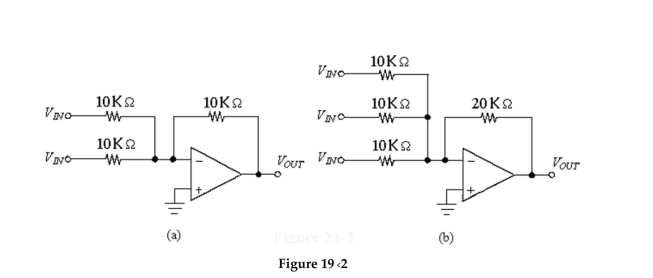
If the two input voltages are 9.2 V and 0.7 V in Figure 19-2(a),W hat is the output voltage?
A)-8.5V
B)-9.9V
C)8.5V
D)9.9V
Question
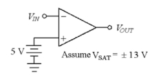
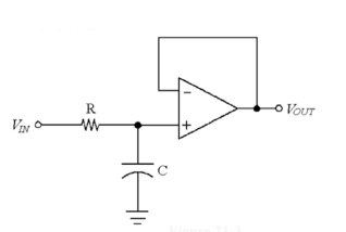
-If VIN equals 8 V in Figure 19-1, VOUT equals_______
A) -1 V
B) 1 V
C) 13 V
D) -13 V
Question
Question
-If VIN equals 4 V in Figure 19-1, VOUT equals__________
A) -13 V
B) 13 V
C) -1 V
D) 1 V
Question
If the inputs are 8.4 V and 1.2 V in Figure 19-2(a), the output voltage equals ________.
A)9.6V
B)-9.6V
C)10.08V
D)7.2V
Question
What change causes the circuit in Figure 19-2(b) to output the average of the three input voltages?
A) Change the input resistors to 3.3

B) Change the feedback resistor to 3.3

C) Change to a different type of op-amp.
D) Change the feedback resistor to 10

Question
If the inputs are -7.1 V and 12 V in Figure 19-2(a),W hat is the output voltage?
A)4.9V
B)-4.9V
C)19.1V
D)-19.1V
Question
Question
-If VIN=-3 V in Figure 19-1, VOUT equals________
A) -13 V
B) 13 V
C) -1 V
D) 1 V
Question
Question
Question
-If VIN=8.3 V in Figure 19-1, VOUT e quals________
A) 3.3 V
B) -3.3 V
C) -13 V
D) 13 V
Question
If the inputs are 4.1 V, -0.7 V and 3.1 V in Figure 19-2(b), the output voltage equals ________.
A)-6.5V
B)13V
C)-13V
D)6.5V
Question
-If VIN=4.2 V in Figure 19-1, VOUT equals__________
A) -0.8 V
B) 0.8 V
C) 13 V
D) -13 V
Question
Question
Question
-If VIN=-2 V in Figure 19-1, VOUT equals______
A) 13 V
B) -3 V
C) 3 V
D) -13 V
Question
Question
-The circuit in Figure 19-4 is known as the____ and it rolls off at a rate of________
A) Butterworth high-pass filter, -40 dB /decade
B) Butterworth low-pass filter, -40 dB/decade
C) Butterworth low-pass filter, -20 dB/decade
D) Butterworth high-pass filter, -20 dB/decade
Question
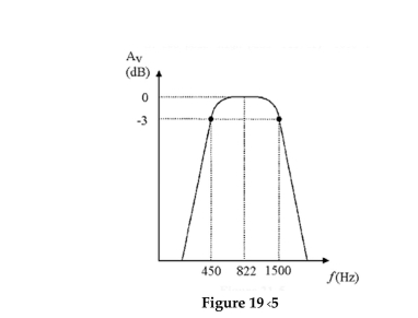
The curve in Figure 19-5 is from a ________ and its lower cutoff frequency equals ________.
A)two-pole high-pass filter, 1500 Hz
B)band-reject filter, 450 kHz
C)band-pass filter, 822 Hz
D)band-pass filter, 450 Hz
Question
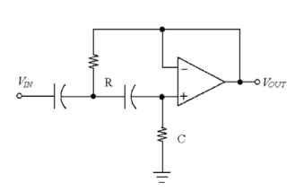
-If R=1.2 and C=0.005 in Figure 19-3, the equals________
A) 65 Hz
B) 650 Hz
C) 26.5 kHz
D) 2.65 kHz
Question
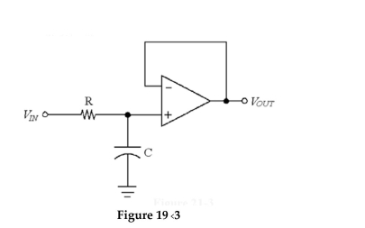
In Figure 19-3,W hatW ill change the circuit into a high-pass filter?
A)increasing theV
Alue of the resistor
B)switching the positions of the resistor and capacitor
C)decreasing theV
Alue of the capacitor
D)placing the capacitor in the feedback loop
Question
-If R=47 and C=0.02 in Figure 19-3, equals______
A) 5.19 Hz
B) 16.9 Hz
C) 169 Hz
D) 51.9 Hz
Question
-If R=1.5 and C=256 pF in Figure 19-3 , the fCO equals_______
A) 41.4 kHz
B) 25.7 Hz
C) 257 Hz
D) 414 kHz
Question
-If R=56 and C=0.05 in Figure 19-3, equals_____
A) 568 Mz
B) 56.8 Hz
C) 3.0 Hz
D) 300 Hz
Question
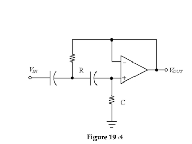
If 22 V in the pass-band is input to the circuit in Figure 19-4,W hat is the output voltage at fCO?
A)8.92V
B)7.75V
C)31.1V
D)15.6V
Question
If the inputs are 1.2 V, -0.5 V and 2.4 V in Figure 19-2(b),W hat is the output voltage?
A)13V
B)-6.2V
C)6.2V
D)-4.1V
Question
Question
-If VIN equals 22 V in Figure 19-3, VOUT at the fCO equals______
A) 31.1 V
B) 15.64 V
C) 0
D) 7.79 V
Question
-If VIN=70 VP in Figure 19-3, the output voltage at fCO equals______
A) 13 VP
B) 0 VP
C) 49.5 VP
D) 44.2 VP
Question
If VOUT equals 12 V at 822 Hz in Figure 19-5, the output voltage equals ________ at 450 Hz.
A)4.24V
B)1.06V
C)8.49V
D)2.12V
Question
If 22 V in the pass-band is input to the circuit in Figure 19-4,W hat is the output voltage at a frequency that is 1 decade higher?
A)31.1V
B)22V
C)7.75V
D)15.5V
Question
In Figure 19-4, if the frequency is decreased from the pass band to 1 decade below fCO, the output voltage drops to ________.
A)-40 dB
B)-6 dB
C)-3 dB
D)-20 dB
Question
-If R=22 and C=0.05 in Figure 19-3, fCO equals________
A) 145 Hz
B) 4.8 Hz
C) 48 Hz
D) 1.45 kHz
Question
-The prime characteristic of the filter in Figure 19-4 is ________.
A)it only works in a high-pass configuration
B)the filter roll-off below the corner frequency is 40 dB/decade
C)it has the largest response of any filter type
D)nothing special
Question
The frequency response curve in Figure 19-5 represents the output from the ________, and the bandwidth is ________.
A)band-pass filter, 1050 Hz
B)band-pass filter, 678 Hz
C)band-reject filter, 1050 kHz
D)two-pole high-pass filter, 1050 Hz
Question
If the output voltage is 6 V at 1500 Hz in Figure 19-5,W hat is the output voltage at 822 Hz?
A)4.24V
B)1.06V
C)8.49V
D)2.12V
Question
If the output voltage is 27.4 V at 822 Hz in Figure 19-5,W hat is the output voltage at 1.5 kHz?
A)27.4V
B)13.7V
C)6.85V
D)19.4V
Question
Question
Question
Question
Question
Question
Question
Question
Question
Question
Question
Question
Question
Question
Question
Question
Question
Question
Question
Question
Question
Question
If
 and
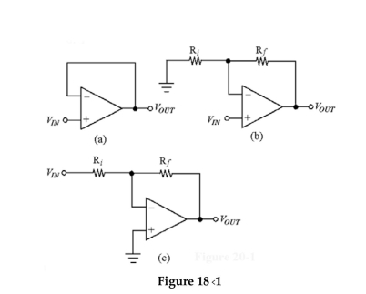
and  in Figure 18-1(c), the voltage gain equals
A) -38.3
B) -1
C) -39.3
D) infinite
Question
Figure
-VRF equals____ in Figure 18-1(c).
A) VRI
B) VOUT
C) VIN
D) VCC
Question
Question
Question
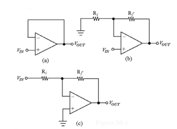
What is the voltage gain of the amplifier in Figure 18-1(a)?
A)1000
B)1
C)100,000
D)10
Question
Identify the open-loop amplifier in Figure 18-1.
A)Figure 18-1(a)
B)Figure 18-1(b)
C)Figure 18-1(c)
D)none of these
Question
Question
Figure
-If and in Figure 18-1(b), the voltage gain equals________
A) 6
B) 5
C) 50
D) 51
Question
Figure
-If and in Figure 18-1(b), the voltage gain equals_________
A) 1.01
B) 470
C) 94
D) 95
Question
Question
Question
Question
Question
Question
The circuit in Figure 18-1(c)is known as the ________.
A)open-loop amplifier
B)voltage follower amplifier
C)non-inverting amplifier
D)inverting amplifier
Question
Figure
-If and AV=120 in Figure 18-1( c), Ri equals___________
A) 1
B) 10
C) 120
D) 100
Question
Question
Identify the non-inverting amplifier in Figure 18-1.
A)Figure 18-1(a)
B)Figure 18-1(b)
C)Both A and B
D)Neither of these
Question
Which of the amplifiers in Figure 18-1W ould be used as a buffer amplifier?
A)Figure 18-1(a)
B)Figure 18-1(b)
C)Figure 18-1(c)
D)none of these

Unlock Deck
Sign up to unlock the cards in this deck!
Unlock Deck
Unlock Deck
1/307
Play
Full screen (f)
Deck 16: Regulators, Filters, and Op-Amps
1
Op-amp comparators are often used as zero-level detectors.
True
2
An op-amp summing amplifier has no limitations on the number of inputs it can handle.
True
3
If the two input voltages are 9.2 V and 0.7 V in Figure 19-2(a),W hat is the output voltage?
A)-8.5V
B)-9.9V
C)8.5V
D)9.9V
-9.9V
4
-If VIN equals 8 V in Figure 19-1, VOUT equals_______
A) -1 V
B) 1 V
C) 13 V
D) -13 V
Unlock Deck
Unlock for access to all 307 flashcards in this deck.
Unlock Deck
k this deck
5
A series-pass transistor is used in a voltage regulator.
Unlock Deck
Unlock for access to all 307 flashcards in this deck.
Unlock Deck
k this deck
6
-If VIN equals 4 V in Figure 19-1, VOUT equals__________
A) -13 V
B) 13 V
C) -1 V
D) 1 V
Unlock Deck
Unlock for access to all 307 flashcards in this deck.
Unlock Deck
k this deck
7
If the inputs are 8.4 V and 1.2 V in Figure 19-2(a), the output voltage equals ________.
A)9.6V
B)-9.6V
C)10.08V
D)7.2V
Unlock Deck
Unlock for access to all 307 flashcards in this deck.
Unlock Deck
k this deck
8
What change causes the circuit in Figure 19-2(b) to output the average of the three input voltages?
A) Change the input resistors to 3.3
B) Change the feedback resistor to 3.3
C) Change to a different type of op-amp.
D) Change the feedback resistor to 10
Unlock Deck
Unlock for access to all 307 flashcards in this deck.
Unlock Deck
k this deck
9
If the inputs are -7.1 V and 12 V in Figure 19-2(a),W hat is the output voltage?
A)4.9V
B)-4.9V
C)19.1V
D)-19.1V
Unlock Deck
Unlock for access to all 307 flashcards in this deck.
Unlock Deck
k this deck
10
Butter worth filters are characterized by a linear response in the pass band.
Unlock Deck
Unlock for access to all 307 flashcards in this deck.
Unlock Deck
k this deck
11
-If VIN=-3 V in Figure 19-1, VOUT equals________
A) -13 V
B) 13 V
C) -1 V
D) 1 V
Unlock Deck
Unlock for access to all 307 flashcards in this deck.
Unlock Deck
k this deck
12
Hartley and Colpitts oscillators can use op-amps.
Unlock Deck
Unlock for access to all 307 flashcards in this deck.
Unlock Deck
k this deck
13
The terminals on a three-terminal regulator are input voltage, output voltage and ground.
Unlock Deck
Unlock for access to all 307 flashcards in this deck.
Unlock Deck
k this deck
14
-If VIN=8.3 V in Figure 19-1, VOUT e quals________
A) 3.3 V
B) -3.3 V
C) -13 V
D) 13 V
Unlock Deck
Unlock for access to all 307 flashcards in this deck.
Unlock Deck
k this deck
15
If the inputs are 4.1 V, -0.7 V and 3.1 V in Figure 19-2(b), the output voltage equals ________.
A)-6.5V
B)13V
C)-13V
D)6.5V
Unlock Deck
Unlock for access to all 307 flashcards in this deck.
Unlock Deck
k this deck
16
-If VIN=4.2 V in Figure 19-1, VOUT equals__________
A) -0.8 V
B) 0.8 V
C) 13 V
D) -13 V
Unlock Deck
Unlock for access to all 307 flashcards in this deck.
Unlock Deck
k this deck
17
An op-amp integrator Will produce a linear increasing output voltage for a constant negative input voltage until cutoff is reached.
Unlock Deck
Unlock for access to all 307 flashcards in this deck.
Unlock Deck
k this deck
18
An op-amp comparator can be used to determineW hen an input voltage crosses a certain reference Voltage.
Unlock Deck
Unlock for access to all 307 flashcards in this deck.
Unlock Deck
k this deck
19
-If VIN=-2 V in Figure 19-1, VOUT equals______
A) 13 V
B) -3 V
C) 3 V
D) -13 V
Unlock Deck
Unlock for access to all 307 flashcards in this deck.
Unlock Deck
k this deck
20
A second-order filter rolls-off at 40 dB/decade.
Unlock Deck
Unlock for access to all 307 flashcards in this deck.
Unlock Deck
k this deck
21
-The circuit in Figure 19-4 is known as the____ and it rolls off at a rate of________
A) Butterworth high-pass filter, -40 dB /decade
B) Butterworth low-pass filter, -40 dB/decade
C) Butterworth low-pass filter, -20 dB/decade
D) Butterworth high-pass filter, -20 dB/decade
Unlock Deck
Unlock for access to all 307 flashcards in this deck.
Unlock Deck
k this deck
22
The curve in Figure 19-5 is from a ________ and its lower cutoff frequency equals ________.
A)two-pole high-pass filter, 1500 Hz
B)band-reject filter, 450 kHz
C)band-pass filter, 822 Hz
D)band-pass filter, 450 Hz
Unlock Deck
Unlock for access to all 307 flashcards in this deck.
Unlock Deck
k this deck
23
-If R=1.2 and C=0.005 in Figure 19-3, the equals________
A) 65 Hz
B) 650 Hz
C) 26.5 kHz
D) 2.65 kHz
Unlock Deck
Unlock for access to all 307 flashcards in this deck.
Unlock Deck
k this deck
24
In Figure 19-3,W hatW ill change the circuit into a high-pass filter?
A)increasing theV
Alue of the resistor
B)switching the positions of the resistor and capacitor
C)decreasing theV
Alue of the capacitor
D)placing the capacitor in the feedback loop
Unlock Deck
Unlock for access to all 307 flashcards in this deck.
Unlock Deck
k this deck
25
-If R=47 and C=0.02 in Figure 19-3, equals______
A) 5.19 Hz
B) 16.9 Hz
C) 169 Hz
D) 51.9 Hz
Unlock Deck
Unlock for access to all 307 flashcards in this deck.
Unlock Deck
k this deck
26
-If R=1.5 and C=256 pF in Figure 19-3 , the fCO equals_______
A) 41.4 kHz
B) 25.7 Hz
C) 257 Hz
D) 414 kHz
Unlock Deck
Unlock for access to all 307 flashcards in this deck.
Unlock Deck
k this deck
27
-If R=56 and C=0.05 in Figure 19-3, equals_____
A) 568 Mz
B) 56.8 Hz
C) 3.0 Hz
D) 300 Hz
Unlock Deck
Unlock for access to all 307 flashcards in this deck.
Unlock Deck
k this deck
28
If 22 V in the pass-band is input to the circuit in Figure 19-4,W hat is the output voltage at fCO?
A)8.92V
B)7.75V
C)31.1V
D)15.6V
Unlock Deck
Unlock for access to all 307 flashcards in this deck.
Unlock Deck
k this deck
29
If the inputs are 1.2 V, -0.5 V and 2.4 V in Figure 19-2(b),W hat is the output voltage?
A)13V
B)-6.2V
C)6.2V
D)-4.1V
Unlock Deck
Unlock for access to all 307 flashcards in this deck.
Unlock Deck
k this deck
30
A three-terminal voltage regulator ________.
A)comes in a variety of Voltage and current ratings
B)is available in both positive and negative Voltage ratings
C)is very durable
D)all of the above
A)comes in a variety of Voltage and current ratings
B)is available in both positive and negative Voltage ratings
C)is very durable
D)all of the above
Unlock Deck
Unlock for access to all 307 flashcards in this deck.
Unlock Deck
k this deck
31
-If VIN equals 22 V in Figure 19-3, VOUT at the fCO equals______
A) 31.1 V
B) 15.64 V
C) 0
D) 7.79 V
Unlock Deck
Unlock for access to all 307 flashcards in this deck.
Unlock Deck
k this deck
32
-If VIN=70 VP in Figure 19-3, the output voltage at fCO equals______
A) 13 VP
B) 0 VP
C) 49.5 VP
D) 44.2 VP
Unlock Deck
Unlock for access to all 307 flashcards in this deck.
Unlock Deck
k this deck
33
If VOUT equals 12 V at 822 Hz in Figure 19-5, the output voltage equals ________ at 450 Hz.
A)4.24V
B)1.06V
C)8.49V
D)2.12V
Unlock Deck
Unlock for access to all 307 flashcards in this deck.
Unlock Deck
k this deck
34
If 22 V in the pass-band is input to the circuit in Figure 19-4,W hat is the output voltage at a frequency that is 1 decade higher?
A)31.1V
B)22V
C)7.75V
D)15.5V
Unlock Deck
Unlock for access to all 307 flashcards in this deck.
Unlock Deck
k this deck
35
In Figure 19-4, if the frequency is decreased from the pass band to 1 decade below fCO, the output voltage drops to ________.
A)-40 dB
B)-6 dB
C)-3 dB
D)-20 dB
Unlock Deck
Unlock for access to all 307 flashcards in this deck.
Unlock Deck
k this deck
36
-If R=22 and C=0.05 in Figure 19-3, fCO equals________
A) 145 Hz
B) 4.8 Hz
C) 48 Hz
D) 1.45 kHz
Unlock Deck
Unlock for access to all 307 flashcards in this deck.
Unlock Deck
k this deck
37
-The prime characteristic of the filter in Figure 19-4 is ________.
A)it only works in a high-pass configuration
B)the filter roll-off below the corner frequency is 40 dB/decade
C)it has the largest response of any filter type
D)nothing special
Unlock Deck
Unlock for access to all 307 flashcards in this deck.
Unlock Deck
k this deck
38
The frequency response curve in Figure 19-5 represents the output from the ________, and the bandwidth is ________.
A)band-pass filter, 1050 Hz
B)band-pass filter, 678 Hz
C)band-reject filter, 1050 kHz
D)two-pole high-pass filter, 1050 Hz
Unlock Deck
Unlock for access to all 307 flashcards in this deck.
Unlock Deck
k this deck
39
If the output voltage is 6 V at 1500 Hz in Figure 19-5,W hat is the output voltage at 822 Hz?
A)4.24V
B)1.06V
C)8.49V
D)2.12V
Unlock Deck
Unlock for access to all 307 flashcards in this deck.
Unlock Deck
k this deck
40
If the output voltage is 27.4 V at 822 Hz in Figure 19-5,W hat is the output voltage at 1.5 kHz?
A)27.4V
B)13.7V
C)6.85V
D)19.4V
Unlock Deck
Unlock for access to all 307 flashcards in this deck.
Unlock Deck
k this deck
41
A series-pass voltage regulator has ________.
A)a load
B)a shunt regulator
C)an error amplifier
D)all of these
A)a load
B)a shunt regulator
C)an error amplifier
D)all of these
Unlock Deck
Unlock for access to all 307 flashcards in this deck.
Unlock Deck
k this deck
42
A series and a shunt regulator are differentiated by the circuit placement of a:
A)series resistor versus parallel resistor.
B)series transistor versus parallel transistor.
C)series reference Voltage versus parallel reference Voltage.
D)none of these.
A)series resistor versus parallel resistor.
B)series transistor versus parallel transistor.
C)series reference Voltage versus parallel reference Voltage.
D)none of these.
Unlock Deck
Unlock for access to all 307 flashcards in this deck.
Unlock Deck
k this deck
43
In a series voltage regulator, the four circuit blocks are:
A)error detector, referenceVoltage, series regulator, sampling circuit.
B)control element, referenceVoltage, error detector, sampling circuit.
C)referenceVoltage, series load, referenceVoltage, current limiter.
D)control element, referenceVoltage, error detector, current limiter.
A)error detector, referenceVoltage, series regulator, sampling circuit.
B)control element, referenceVoltage, error detector, sampling circuit.
C)referenceVoltage, series load, referenceVoltage, current limiter.
D)control element, referenceVoltage, error detector, current limiter.
Unlock Deck
Unlock for access to all 307 flashcards in this deck.
Unlock Deck
k this deck
44
At the cutoff frequency of a filter circuit, the output voltage is:
A)-20 dB.
B)-40 dB.
C)-3 dB.
D)-10 dB.
A)-20 dB.
B)-40 dB.
C)-3 dB.
D)-10 dB.
Unlock Deck
Unlock for access to all 307 flashcards in this deck.
Unlock Deck
k this deck
45
Short-circuit or overload protection is an integral part of
A) most JFETs
B) most three-terminal regulators
C) most op-amps
D) most TRIACs
A) most JFETs
B) most three-terminal regulators
C) most op-amps
D) most TRIACs
Unlock Deck
Unlock for access to all 307 flashcards in this deck.
Unlock Deck
k this deck
46
The output of an op-amp differentiator depends on the values of ________ and ________.
A)CIN, CF
B)RIN, RF
C)RIN, CF
D)CIN, RF
A)CIN, CF
B)RIN, RF
C)RIN, CF
D)CIN, RF
Unlock Deck
Unlock for access to all 307 flashcards in this deck.
Unlock Deck
k this deck
47
In an inverting input op-amp, differentiator suppliedW ith a ramp or triangularW ave, the output is a:
A)opposite phase ramp.
B)same phase square Wave.
C)sine Wave.
D)opposite phase square Wave.
A)opposite phase ramp.
B)same phase square Wave.
C)sine Wave.
D)opposite phase square Wave.
Unlock Deck
Unlock for access to all 307 flashcards in this deck.
Unlock Deck
k this deck
48
The purpose of a comparator is to ________.
A)detect the occurrence of a changing input voltage
B)produce a change in output when an input voltage equals a reference voltage
C)maintain a constant output when the dc inputVoltage changes
D)amplify an input voltage
A)detect the occurrence of a changing input voltage
B)produce a change in output when an input voltage equals a reference voltage
C)maintain a constant output when the dc inputVoltage changes
D)amplify an input voltage
Unlock Deck
Unlock for access to all 307 flashcards in this deck.
Unlock Deck
k this deck
49
Using op-amps in a triangularW ave oscillator results in a:
A)triangular Wave output.
B)function generator output.
C)square Wave output.
D)all of these.
A)triangular Wave output.
B)function generator output.
C)square Wave output.
D)all of these.
Unlock Deck
Unlock for access to all 307 flashcards in this deck.
Unlock Deck
k this deck
50
If all four input resistors to a summing amplifier are 2.2 and the feedback resistor is 2.2 . then the gain equals________
A) 4
B) 2.2
C) 1
D) unknown
A) 4
B) 2.2
C) 1
D) unknown
Unlock Deck
Unlock for access to all 307 flashcards in this deck.
Unlock Deck
k this deck
51
In a scaling adder, the ________.
A)input resistors have values depending on the assigned weight of each input
B)input resistors are all different values
C)input resistors are all the same value
D)ratio RF/RIN must be the same for each input
A)input resistors have values depending on the assigned weight of each input
B)input resistors are all different values
C)input resistors are all the same value
D)ratio RF/RIN must be the same for each input
Unlock Deck
Unlock for access to all 307 flashcards in this deck.
Unlock Deck
k this deck
52
In a filter circuit, the terminology single pole means:
A)one fixed contact.
B)one single RC circuit.
C)one movable contact.
D)two cascaded RC circuits.
A)one fixed contact.
B)one single RC circuit.
C)one movable contact.
D)two cascaded RC circuits.
Unlock Deck
Unlock for access to all 307 flashcards in this deck.
Unlock Deck
k this deck
53
The basic op-amp squareW ave oscillator is actually a:
A)Wein-bridge oscillator.
B)resistor-capacitor (RC)time constant oscillator.
C)sine Wave oscillator.
D)all of these.
A)Wein-bridge oscillator.
B)resistor-capacitor (RC)time constant oscillator.
C)sine Wave oscillator.
D)all of these.
Unlock Deck
Unlock for access to all 307 flashcards in this deck.
Unlock Deck
k this deck
54
The input frequency of a single-pole, low-pass active filter increases from 1.5 kHz to 150 kHz. If the critical frequency is 1.5 kHz, the gain decreases by ________.
A)60 dB
B)3 dB
C)40 dB
D)20 dB
A)60 dB
B)3 dB
C)40 dB
D)20 dB
Unlock Deck
Unlock for access to all 307 flashcards in this deck.
Unlock Deck
k this deck
55
If an inverting amplifier has a capacitor in the feedback loop, the circuit is known as the ________. When a square wave input is applied, the output is a ________wave.
A)integrator, square
B)open loop, triangle
C)differentiator, triangle
D)integrator, triangle
A)integrator, square
B)open loop, triangle
C)differentiator, triangle
D)integrator, triangle
Unlock Deck
Unlock for access to all 307 flashcards in this deck.
Unlock Deck
k this deck
56
The ideal amplifier has infinite gain, infinite input impedance, and zero output impedance.
Unlock Deck
Unlock for access to all 307 flashcards in this deck.
Unlock Deck
k this deck
57
In a Wein-bridge op-amp oscillator, the output is a repetitive:
A)square Wave.
B)sine Wave.
C)triangular Wave.
D)all of these.
A)square Wave.
B)sine Wave.
C)triangular Wave.
D)all of these.
Unlock Deck
Unlock for access to all 307 flashcards in this deck.
Unlock Deck
k this deck
58
In a voltage-controlled oscillator (VCO), the output signal frequency is dependent on:
A)the value of a resistor-capacitor combination.
B)the value of a resistor.
C)the value of an applied Voltage.
D)the value of a capacitor.
A)the value of a resistor-capacitor combination.
B)the value of a resistor.
C)the value of an applied Voltage.
D)the value of a capacitor.
Unlock Deck
Unlock for access to all 307 flashcards in this deck.
Unlock Deck
k this deck
59
In an inverting input op-amp integrator suppliedW ith a squareW ave pulse or a step, the output is a:
A)opposite phase ramp.
B)same phase ramp.
C)opposite phase square Wave.
D)sine Wave.
A)opposite phase ramp.
B)same phase ramp.
C)opposite phase square Wave.
D)sine Wave.
Unlock Deck
Unlock for access to all 307 flashcards in this deck.
Unlock Deck
k this deck
60
If all four input resistors to a summing amplifier are 2.2 , the feedback resistor is 2.2 and all four input voltages are -2 V , the output voltage equals_______
A) 2 V
B) 2.2 V
C) 8 V
D) 10 V
A) 2 V
B) 2.2 V
C) 8 V
D) 10 V
Unlock Deck
Unlock for access to all 307 flashcards in this deck.
Unlock Deck
k this deck
61
The open-loop voltage gain of an op-amp is very large.
Unlock Deck
Unlock for access to all 307 flashcards in this deck.
Unlock Deck
k this deck
62
If
and in Figure 18-1(c), the voltage gain equalsA) -38.3
B) -1
C) -39.3
D) infinite
Unlock Deck
Unlock for access to all 307 flashcards in this deck.
Unlock Deck
k this deck
63
Figure
-VRF equals____ in Figure 18-1(c).
A) VRI
B) VOUT
C) VIN
D) VCC
Unlock Deck
Unlock for access to all 307 flashcards in this deck.
Unlock Deck
k this deck
64
The slew rate of an op-amp is determined by the frequency response of the internal amplifiers.
Unlock Deck
Unlock for access to all 307 flashcards in this deck.
Unlock Deck
k this deck
65
Which one of these op-amp terminals provides an output that is in-phase with the input?
A) offset null
B) non-inverting
C) VCC
D) inverting
A) offset null
B) non-inverting
C) VCC
D) inverting
Unlock Deck
Unlock for access to all 307 flashcards in this deck.
Unlock Deck
k this deck
66
What is the voltage gain of the amplifier in Figure 18-1(a)?
A)1000
B)1
C)100,000
D)10
Unlock Deck
Unlock for access to all 307 flashcards in this deck.
Unlock Deck
k this deck
67
Identify the open-loop amplifier in Figure 18-1.
A)Figure 18-1(a)
B)Figure 18-1(b)
C)Figure 18-1(c)
D)none of these
Unlock Deck
Unlock for access to all 307 flashcards in this deck.
Unlock Deck
k this deck
68
A voltage-follower op-amp has a voltage gain greater than one.
Unlock Deck
Unlock for access to all 307 flashcards in this deck.
Unlock Deck
k this deck
69
Figure
-If and in Figure 18-1(b), the voltage gain equals________
A) 6
B) 5
C) 50
D) 51
Unlock Deck
Unlock for access to all 307 flashcards in this deck.
Unlock Deck
k this deck
70
Figure
-If and in Figure 18-1(b), the voltage gain equals_________
A) 1.01
B) 470
C) 94
D) 95
Unlock Deck
Unlock for access to all 307 flashcards in this deck.
Unlock Deck
k this deck
71
An op-ampʹs input offset voltage, VOS, is the differential input voltage required to make the differential output voltage zero.
Unlock Deck
Unlock for access to all 307 flashcards in this deck.
Unlock Deck
k this deck
72
An op-ampW ith a low CMRR easily rejects noise signals that appear at both inputs.
Unlock Deck
Unlock for access to all 307 flashcards in this deck.
Unlock Deck
k this deck
73
Differential amplifiers provide high voltage gain and low common-mode rejection.
Unlock Deck
Unlock for access to all 307 flashcards in this deck.
Unlock Deck
k this deck
74
Practical op-amps come reasonably close to the requirements for an ideal amplifier.
Unlock Deck
Unlock for access to all 307 flashcards in this deck.
Unlock Deck
k this deck
75
An op-ampʹs CMRR is usually expressed in dB.
Unlock Deck
Unlock for access to all 307 flashcards in this deck.
Unlock Deck
k this deck
76
The circuit in Figure 18-1(c)is known as the ________.
A)open-loop amplifier
B)voltage follower amplifier
C)non-inverting amplifier
D)inverting amplifier
Unlock Deck
Unlock for access to all 307 flashcards in this deck.
Unlock Deck
k this deck
77
Figure
-If and AV=120 in Figure 18-1( c), Ri equals___________
A) 1
B) 10
C) 120
D) 100
Unlock Deck
Unlock for access to all 307 flashcards in this deck.
Unlock Deck
k this deck
78
A typical value of input bias current for an op-amp is around 80 nA.
Unlock Deck
Unlock for access to all 307 flashcards in this deck.
Unlock Deck
k this deck
79
Identify the non-inverting amplifier in Figure 18-1.
A)Figure 18-1(a)
B)Figure 18-1(b)
C)Both A and B
D)Neither of these
Unlock Deck
Unlock for access to all 307 flashcards in this deck.
Unlock Deck
k this deck
80
Which of the amplifiers in Figure 18-1W ould be used as a buffer amplifier?
A)Figure 18-1(a)
B)Figure 18-1(b)
C)Figure 18-1(c)
D)none of these
Unlock Deck
Unlock for access to all 307 flashcards in this deck.
Unlock Deck
k this deck
Unlock Deck
Unlock for access to all 307 flashcards in this deck.


