Deck 8: Multiple Push Button Stations
Full screen (f)
Question
Figure 8-4
What type of diagram is shown in the accompanying figure? What are the numbers which are shown called?
What type of diagram is shown in the accompanying figure? What are the numbers which are shown called?
Question
Question
Question
Question
Question
Figure 8-2
Based on the accompanying figure, what happens to the three load contacts connected between the three phase power line and the motor after either START button is pressed?
Based on the accompanying figure, what happens to the three load contacts connected between the three phase power line and the motor after either START button is pressed?
Question
Figure 8-1
The accompanying figure shows the addition of a(n) ____________________ button to the circuit.
The accompanying figure shows the addition of a(n) ____________________ button to the circuit.
Question
Figure 8-1

Based on the accompanying figure, describe how the additional button is added to the circuit.
Based on the accompanying figure, describe how the additional button is added to the circuit.
Question
Question
Question
Question
Question
Figure 8-5
What type of diagram is shown in the accompanying figure?
What type of diagram is shown in the accompanying figure?
Question
Figure 8-3
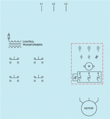
The accompanying figure shows the components needed to produce a wiring diagram.
The accompanying figure shows the components needed to produce a wiring diagram.
Question

Unlock Deck
Sign up to unlock the cards in this deck!
Unlock Deck
Unlock Deck
1/15
Play
Full screen (f)
Deck 8: Multiple Push Button Stations
1
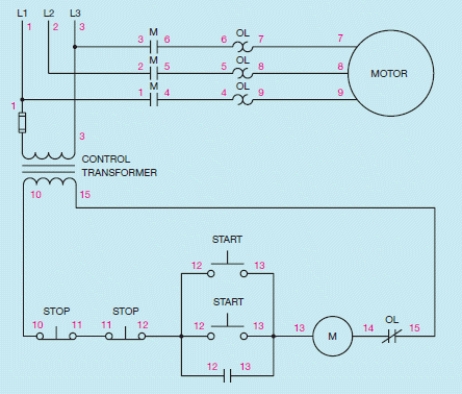
Figure 8-4
What type of diagram is shown in the accompanying figure? What are the numbers which are shown called?
What type of diagram is shown in the accompanying figure? What are the numbers which are shown called?
The accompanying figure shows a schematic or ladder diagram and the numbers shown are called wire numbers.
2
When a component is used to perform the function of stop in a control circuit, it will generally be a normally ____________________ component.
closed
3
When a component is used to perform the function of stop in a control circuit, it will generally be connected in ____________________ with the motor starter coil.
series
4
When M coil energizes, only the first M contact changes position.
Unlock Deck
Unlock for access to all 15 flashcards in this deck.
Unlock Deck
k this deck
5
When a component is used to perform the function of start it is generally normally ____________________.
Unlock Deck
Unlock for access to all 15 flashcards in this deck.
Unlock Deck
k this deck
6
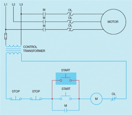
Figure 8-2
Based on the accompanying figure, what happens to the three load contacts connected between the three phase power line and the motor after either START button is pressed?
Based on the accompanying figure, what happens to the three load contacts connected between the three phase power line and the motor after either START button is pressed?
Unlock Deck
Unlock for access to all 15 flashcards in this deck.
Unlock Deck
k this deck
7
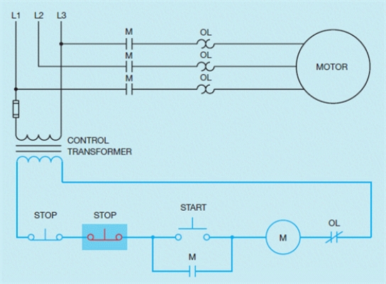
Figure 8-1
The accompanying figure shows the addition of a(n) ____________________ button to the circuit.
The accompanying figure shows the addition of a(n) ____________________ button to the circuit.
Unlock Deck
Unlock for access to all 15 flashcards in this deck.
Unlock Deck
k this deck
8
Figure 8-1
Based on the accompanying figure, describe how the additional button is added to the circuit.
Based on the accompanying figure, describe how the additional button is added to the circuit.
Unlock Deck
Unlock for access to all 15 flashcards in this deck.
Unlock Deck
k this deck
9
There may be times when it is desirable to have more than one START-STOP push button station to control a motor.
Unlock Deck
Unlock for access to all 15 flashcards in this deck.
Unlock Deck
k this deck
10
When a component is used to perform the function of start it is generally connected in ____________________ with the existing START button.
Unlock Deck
Unlock for access to all 15 flashcards in this deck.
Unlock Deck
k this deck
11
The basic START-STOP push button control circuit discussed in Chapter 7 can be modified to include a second STOP and START push button.
Unlock Deck
Unlock for access to all 15 flashcards in this deck.
Unlock Deck
k this deck
12
Based on the accompanying figure, what happens if either START button is pressed?
Unlock Deck
Unlock for access to all 15 flashcards in this deck.
Unlock Deck
k this deck
13
Figure 8-5
What type of diagram is shown in the accompanying figure?
What type of diagram is shown in the accompanying figure?
Unlock Deck
Unlock for access to all 15 flashcards in this deck.
Unlock Deck
k this deck
14
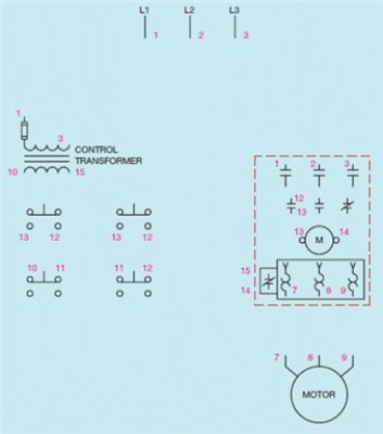
Figure 8-3
The accompanying figure shows the components needed to produce a wiring diagram.
The accompanying figure shows the components needed to produce a wiring diagram.
Unlock Deck
Unlock for access to all 15 flashcards in this deck.
Unlock Deck
k this deck
15
A wiring diagram cannot be developed from a schematic.
Unlock Deck
Unlock for access to all 15 flashcards in this deck.
Unlock Deck
k this deck
Unlock Deck
Unlock for access to all 15 flashcards in this deck.


