Deck 41: Developing Control Circuits
Full screen (f)
Question
Question
Figure 41-4
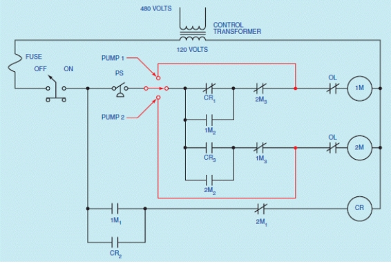
In the accompanying figure, what happens when the pressure switch opens?
In the accompanying figure, what happens when the pressure switch opens?
Question
Figure 41-1
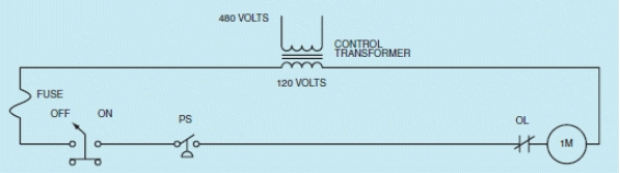
In the accompanying figure, why must the pressure switch be connected as normally closed?
In the accompanying figure, why must the pressure switch be connected as normally closed?
Question
Figure 41-08
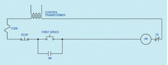
In the accompanying diagram, when the FIRST SPEED button is pressed, motor starter coil 1M will close and connect the stator of the motor to the power line.
In the accompanying diagram, when the FIRST SPEED button is pressed, motor starter coil 1M will close and connect the stator of the motor to the power line.
Question
Question
Figure 41-5
In the accompanying figure, a(n) ____________________ switch is connected to the output of the pressure switch.
In the accompanying figure, a(n) ____________________ switch is connected to the output of the pressure switch.
Question
Figure 41-7
In the accompanying figure, what is the function of load contacts 1M?
In the accompanying figure, what is the function of load contacts 1M?
Question
Figure 41-7

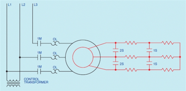
In the accompanying figure, speed control for a wound rotor motor is obtained by placing resistance in the secondary or rotor circuit.
In the accompanying figure, speed control for a wound rotor motor is obtained by placing resistance in the secondary or rotor circuit.
Question
Figure 41-1

In the accompanying figure, a(n) ____________________ is used as short-circuit protection for the control wiring.
In the accompanying figure, a(n) ____________________ is used as short-circuit protection for the control wiring.
Question
Figure 41-5

In the accompanying figure, what does the selector switch permit?
In the accompanying figure, what does the selector switch permit?
Question
Figure 41-7

In the accompanying figure, second speed is obtained by closing ____________________ and shorting out the first three phase resistor bank.
In the accompanying figure, second speed is obtained by closing ____________________ and shorting out the first three phase resistor bank.
Question
Question
Question
Figure 41-02
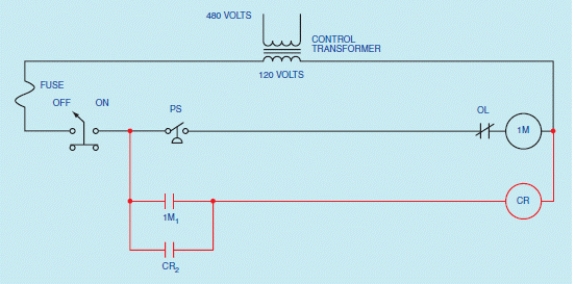
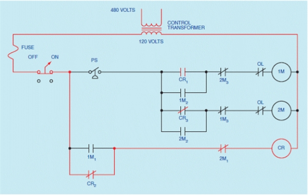
In the accompanying figure, because control relay CR is used as a(n) ____________________, it must be permitted to remain energized when either or both of the motor starters are not energized.
In the accompanying figure, because control relay CR is used as a(n) ____________________, it must be permitted to remain energized when either or both of the motor starters are not energized.
Question
Figure 41-3
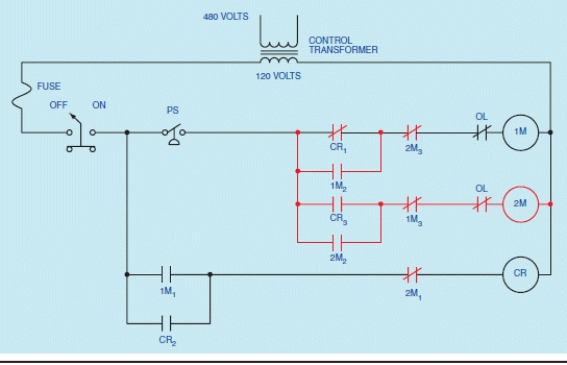
In the accompanying figure, each motor starter coil is protected by a separate overload contact.
In the accompanying figure, each motor starter coil is protected by a separate overload contact.

Unlock Deck
Sign up to unlock the cards in this deck!
Unlock Deck
Unlock Deck
1/15
Play
Full screen (f)
Deck 41: Developing Control Circuits
1
In the accompanying figure, auxiliary contact 1M cannot be used as a holding contact.
False
2
Figure 41-4
In the accompanying figure, what happens when the pressure switch opens?
In the accompanying figure, what happens when the pressure switch opens?
When the pressure switch opens, coil 1M will deenergize, permitting all 1M contacts to return to their normal positions.
3
Figure 41-1
In the accompanying figure, why must the pressure switch be connected as normally closed?
In the accompanying figure, why must the pressure switch be connected as normally closed?
It must be connected as normally closed because the pressure switch must close when the pressure drops.
4
Figure 41-08
In the accompanying diagram, when the FIRST SPEED button is pressed, motor starter coil 1M will close and connect the stator of the motor to the power line.
In the accompanying diagram, when the FIRST SPEED button is pressed, motor starter coil 1M will close and connect the stator of the motor to the power line.
Unlock Deck
Unlock for access to all 15 flashcards in this deck.
Unlock Deck
k this deck
5
In the accompanying figure, a(n) ____________________ has been used to step down the 480-volt supply line voltage to 120 volts for use by the control circuit.
Unlock Deck
Unlock for access to all 15 flashcards in this deck.
Unlock Deck
k this deck
6
Figure 41-5
In the accompanying figure, a(n) ____________________ switch is connected to the output of the pressure switch.
In the accompanying figure, a(n) ____________________ switch is connected to the output of the pressure switch.
Unlock Deck
Unlock for access to all 15 flashcards in this deck.
Unlock Deck
k this deck
7
Figure 41-7
In the accompanying figure, what is the function of load contacts 1M?
In the accompanying figure, what is the function of load contacts 1M?
Unlock Deck
Unlock for access to all 15 flashcards in this deck.
Unlock Deck
k this deck
8
Figure 41-7
In the accompanying figure, speed control for a wound rotor motor is obtained by placing resistance in the secondary or rotor circuit.
In the accompanying figure, speed control for a wound rotor motor is obtained by placing resistance in the secondary or rotor circuit.
Unlock Deck
Unlock for access to all 15 flashcards in this deck.
Unlock Deck
k this deck
9
Figure 41-1
In the accompanying figure, a(n) ____________________ is used as short-circuit protection for the control wiring.
In the accompanying figure, a(n) ____________________ is used as short-circuit protection for the control wiring.
Unlock Deck
Unlock for access to all 15 flashcards in this deck.
Unlock Deck
k this deck
10
Figure 41-5
In the accompanying figure, what does the selector switch permit?
In the accompanying figure, what does the selector switch permit?
Unlock Deck
Unlock for access to all 15 flashcards in this deck.
Unlock Deck
k this deck
11
Figure 41-7
In the accompanying figure, second speed is obtained by closing ____________________ and shorting out the first three phase resistor bank.
In the accompanying figure, second speed is obtained by closing ____________________ and shorting out the first three phase resistor bank.
Unlock Deck
Unlock for access to all 15 flashcards in this deck.
Unlock Deck
k this deck
12
The best method of designing a motor control circuit is to solve one requirement at a time.
Unlock Deck
Unlock for access to all 15 flashcards in this deck.
Unlock Deck
k this deck
13
In the accompanying figure, what happens when power is applied to the stator?
Unlock Deck
Unlock for access to all 15 flashcards in this deck.
Unlock Deck
k this deck
14
Figure 41-02
In the accompanying figure, because control relay CR is used as a(n) ____________________, it must be permitted to remain energized when either or both of the motor starters are not energized.
In the accompanying figure, because control relay CR is used as a(n) ____________________, it must be permitted to remain energized when either or both of the motor starters are not energized.
Unlock Deck
Unlock for access to all 15 flashcards in this deck.
Unlock Deck
k this deck
15
Figure 41-3
In the accompanying figure, each motor starter coil is protected by a separate overload contact.
In the accompanying figure, each motor starter coil is protected by a separate overload contact.
Unlock Deck
Unlock for access to all 15 flashcards in this deck.
Unlock Deck
k this deck
Unlock Deck
Unlock for access to all 15 flashcards in this deck.


