Deck 36: The 555 Pulse Timer
Full screen (f)
Question
In the accompanying figure, when capacitor C1 is charged to two-thirds of Vcc, the output turns off, which turns off relay ____.
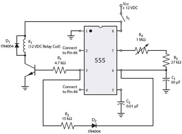
A) R1
B) K1
C) D1
D) S1
A) R1
B) K1
C) D1
D) S1
Question
In the accompanying figure, pin #2 is connected to pin #6, which is at ground potential.

Question
In the accompanying figure, once capacitor C1 has been charged, it is prevented from discharging through resisters R3 and R4.

Question
Question
Question
In the accompanying figure, diode D2 is a ____ diode.

A) stealing
B) free-wheeling
C) blocking
D) locking
A) stealing
B) free-wheeling
C) blocking
D) locking
Question
In the accompanying figure, diode D1 is used as a ____ diode.

A) stealing
B) locking
C) blocking
D) free-wheeling
A) stealing
B) locking
C) blocking
D) free-wheeling
Question
In the accompanying figure, transistor Q2 is used to turn relay coil K1 on or off.

Question
In the accompanying figure, resistor ____ limits the current to the base of the transistor Q1.

A) R1
B) R2
C) R3
D) R4
A) R1
B) R2
C) R3
D) R4
Question
In the accompanying figure, capacitor ____ is charged by a feedback circuit from the output of the timer and not from Vcc.

A) D1
B) C1
C) R1
D) S1
A) D1
B) C1
C) R1
D) S1

Unlock Deck
Sign up to unlock the cards in this deck!
Unlock Deck
Unlock Deck
1/10
Play
Full screen (f)
Deck 36: The 555 Pulse Timer
1
In the accompanying figure, when capacitor C1 is charged to two-thirds of Vcc, the output turns off, which turns off relay ____.
A) R1
B) K1
C) D1
D) S1
A) R1
B) K1
C) D1
D) S1
B
2
In the accompanying figure, pin #2 is connected to pin #6, which is at ground potential.
True
3
In the accompanying figure, once capacitor C1 has been charged, it is prevented from discharging through resisters R3 and R4.
False
4
In a 555 circuit used as a pulse timer, the capacitor is charged by the Vcc and not from a feed-back circuit from the output of the timer.
Unlock Deck
Unlock for access to all 10 flashcards in this deck.
Unlock Deck
k this deck
5
When used as a pulse timer, the 555 timer is connected differently than the 555 timer that is used as an oscillator.
Unlock Deck
Unlock for access to all 10 flashcards in this deck.
Unlock Deck
k this deck
6
In the accompanying figure, diode D2 is a ____ diode.
A) stealing
B) free-wheeling
C) blocking
D) locking
A) stealing
B) free-wheeling
C) blocking
D) locking
Unlock Deck
Unlock for access to all 10 flashcards in this deck.
Unlock Deck
k this deck
7
In the accompanying figure, diode D1 is used as a ____ diode.
A) stealing
B) locking
C) blocking
D) free-wheeling
A) stealing
B) locking
C) blocking
D) free-wheeling
Unlock Deck
Unlock for access to all 10 flashcards in this deck.
Unlock Deck
k this deck
8
In the accompanying figure, transistor Q2 is used to turn relay coil K1 on or off.
Unlock Deck
Unlock for access to all 10 flashcards in this deck.
Unlock Deck
k this deck
9
In the accompanying figure, resistor ____ limits the current to the base of the transistor Q1.
A) R1
B) R2
C) R3
D) R4
A) R1
B) R2
C) R3
D) R4
Unlock Deck
Unlock for access to all 10 flashcards in this deck.
Unlock Deck
k this deck
10
In the accompanying figure, capacitor ____ is charged by a feedback circuit from the output of the timer and not from Vcc.
A) D1
B) C1
C) R1
D) S1
A) D1
B) C1
C) R1
D) S1
Unlock Deck
Unlock for access to all 10 flashcards in this deck.
Unlock Deck
k this deck
Unlock Deck
Unlock for access to all 10 flashcards in this deck.


