The diagram shown is that of a 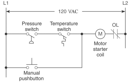
A) hardwired relay schematic.
B) ladder logic program.
C) input module schematic.
D) output module schematic.
Correct Answer:
Verified
Q45: The devices connected to the terminals would
Q46: A control management PLC application normally requires
Q47: The diagram shown is a: 
Q48: Which module of the PLC is responsible
Q49: Block No.6 of the PLC block diagram
Q51: PLC software that runs on a personal
Q52: The voltage that would be present between
Q53: The diagram shown is that of a:
Q54: In order to energize the starter coil:
Q55: For there to be a continuous logic
Unlock this Answer For Free Now!
View this answer and more for free by performing one of the following actions

Scan the QR code to install the App and get 2 free unlocks

Unlock quizzes for free by uploading documents