Multiple Choice
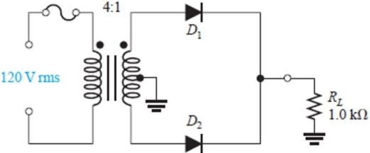 Figure 1
-The circuit in Figure 1 is a
A) clamping circuit
B) bridge rectifier
C) center- tapped full- wave rectifier
D) half- wave rectifier
Correct Answer:
Verified
Related Questions
Q7: The ripple frequency of a bridge rectifier
Q8: Q9: The ideal dc output voltage of a Q10: Another name for a diode limiter circuit Q11: A capacitor filtered half- wave rectifier has Q13: Q14: Assume an ideal diode has a series Q15: The VRRM specification on a manufacturer's data Q16: In a full wave bridge rectifier with Q17: Unlock this Answer For Free Now! View this answer and more for free by performing one of the following actions Scan the QR code to install the App and get 2 free unlocks Unlock quizzes for free by uploading documents![]()
![]()
![]()

