Multiple Choice
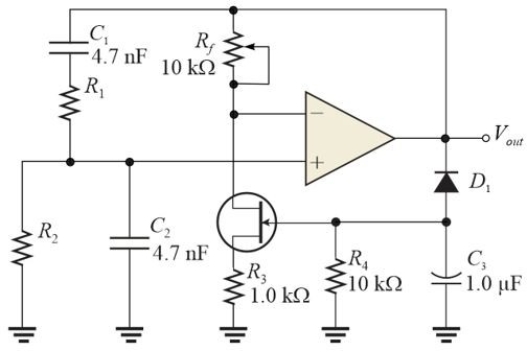 Figure 1
-Refer to Figure 1. When adjusted properly the signal at the non- inverting input of the op- amp is
A) 2/3 Vout
B) 1/3 Vout
C) 1/2 Vout
D) none of the above
Correct Answer:
Verified
Related Questions
Figure 1
-Refer to Figure 1. When adjusted properly the signal at the non- inverting input of the op- amp is
A) 2/3 Vout
B) 1/3 Vout
C) 1/2 Vout
D) none of the above
Correct Answer:
Verified

