For the block diagram of the input module shown, Section #1 represents the ____ and #2 the ____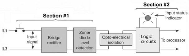 A.
A.
A) AC, DC.
B) DC, AC.
C) power, logic.
D) logic, power.
Correct Answer:
Verified
Q55: The "ON state input voltage range" specification
Q56: Status indicators are provided on each output
Q57: The purpose of the optical isolator is
Q58: The schematic diagram shown is that of
Q59: _ is a type of memory commonly
Q61: The main element of an analog output
Q62: For the PLC analog I/O control system
Q63: High-density I/O modules
A)may have up to 64
Q64: The _ of an analog I/O module
Q65: The processor module of the PLC is
Unlock this Answer For Free Now!
View this answer and more for free by performing one of the following actions

Scan the QR code to install the App and get 2 free unlocks

Unlock quizzes for free by uploading documents