The schematic diagram of Figure 2-6 is an example of how a PLC output module is connected to 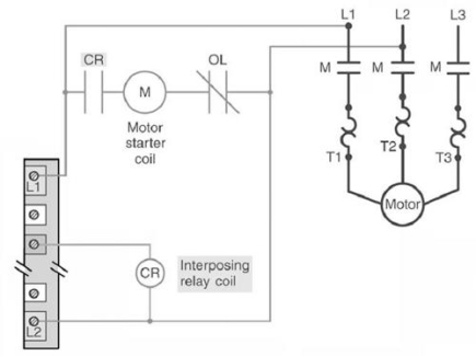
A) isolate the load from the controller.
B) control a high resistance load.
C) vary the speed of a motor.
D) control a high current load.
Correct Answer:
Verified
Q72: When the triac is in the OFF
Q73: Which of the following special I/O modules
Q74: The thermocouple shown is a 
Q75: The schematic diagram shown is that of
Q76: For the thermocouple analog input module shown,
Q78: The input signal to the module comes
Q79: The purpose of the triac switch is
Q80: The current sourcing sensor shown must be
Q81: When placed in the _mode, the processor
Q82: Sinking and sourcing terminology applies to both
Unlock this Answer For Free Now!
View this answer and more for free by performing one of the following actions

Scan the QR code to install the App and get 2 free unlocks

Unlock quizzes for free by uploading documents