Multiple Choice
The diagram shown is a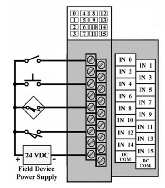
A) relay schematic.
B) ladder logic program.
C) input module wiring.
D) output module wiring.
Correct Answer:
Verified
Related Questions
Q5: Which of the following is not an
Q6: The output interface module connects to
A)sensing devices
Q7: The devices connected to the terminals would
Q8: The central processing unit
A)looks at the inputs,
Q9: In a PLC system, there is a
Q11: The number of I/O points does not
Q12: Plug-in compartments allow I/0 modules to be
Unlock this Answer For Free Now!
View this answer and more for free by performing one of the following actions

Scan the QR code to install the App and get 2 free unlocks

Unlock quizzes for free by uploading documents