Multiple Choice
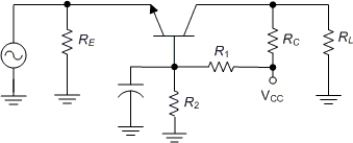
-The circuit in Figure is
A) voltage divider biased.
B) emitter biased.
C) common collector biased.
D) drawn incorrectly. The input should be applied to the base.
Correct Answer:
Verified
Related Questions
-The circuit in Figure is
A) voltage divider biased.
B) emitter biased.
C) common collector biased.
D) drawn incorrectly. The input should be applied to the base.
Correct Answer:
Verified

