Figure 8-1
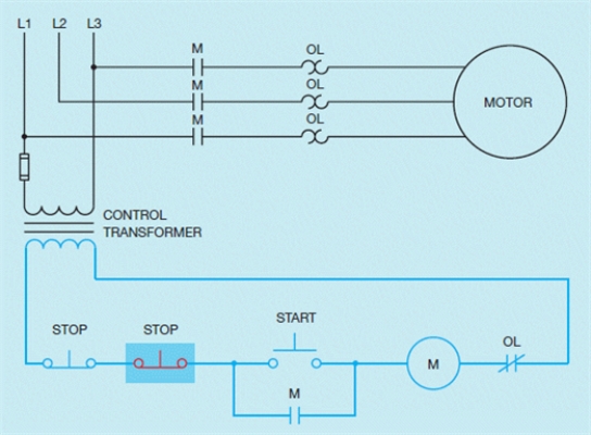
-Based on the accompanying figure, describe how the additional button is added to the circuit.
Correct Answer:
Verified
View Answer
Unlock this answer now
Get Access to more Verified Answers free of charge
Q1: There may be times when it is
Q5: When a component is used to perform
Q6: Figure 8-2 Q7: Figure 8-1 Q7: The basic START-STOP push button control circuit Q8: When M coil energizes, only the first Q9: When a component is used to perform Q12: When a component is used to perform Q12: Based on the accompanying figure, what happens Q13: Figure 8-5 Unlock this Answer For Free Now! View this answer and more for free by performing one of the following actions Scan the QR code to install the App and get 2 free unlocks Unlock quizzes for free by uploading documents
![]()
![]()
![]()

