:}
Neglecting resistance, transformer phase shift, and magnetizing reactance, draw the equivalent reactance diagram. Use a base of and for the 40 -ohm line. Determine the per-unit reactances.
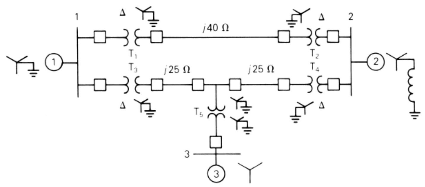
FIGURE P3.11
Correct Answer:
Verified
View Answer
Unlock this answer now
Get Access to more Verified Answers free of charge
Q6: Using the transformer ratings as base quantities,
Q7: A balanced Y-connected voltage source with
Q8: Consider a bank of three single-phase
Q9: The leakage reactance of a three-phase,
Q10: Choosing system bases to be 360/24 kV
Q12: For the power system in Test
Q13: Three single-phase transformers, each rated
Q14: A 100-MVA, 13.2-kV three-phase generator, which
Q15: Figure P3.15 shows a one-line diagram
Q16: A single-phase three-winding transformer has the
Unlock this Answer For Free Now!
View this answer and more for free by performing one of the following actions

Scan the QR code to install the App and get 2 free unlocks

Unlock quizzes for free by uploading documents