In Figure 7-18,the positive supply 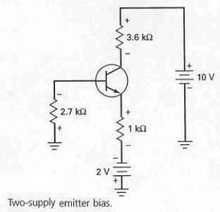
A) forward-biases the collector diode.
B) reverse-biases the collector diode.
C) forward-biases the emitter diode.
D) reverse-biases the emitter diode.
Correct Answer:
Verified
Q20: With the values shown at the operating
Q21: A well-designed voltage-divider bias circuit is one
Q22: To prevent meter loading,a voltmeter used to
Q23: Collector-feedback bias is also called
A) collector-follower bias.
B)
Q24: What type transistor is used when the
Q26: In Figure 7-18,the negative supply 
Q27: The intent of emitter-feedback bias is to
A)
Q28: While troubleshooting the circuit shown in Figure
Q29: By exposing a transistor's collector junction to
Q30: Using a firm voltage divider means that
Unlock this Answer For Free Now!
View this answer and more for free by performing one of the following actions

Scan the QR code to install the App and get 2 free unlocks

Unlock quizzes for free by uploading documents