The output as measured across RL in Figure 4-6 (a) would be 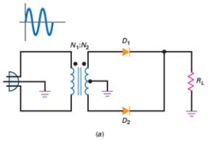
A) pulsating dc.
B) alternating current.
C) negative dc pulses.
D) a square wave.
Correct Answer:
Verified
Q35: When neither end of a load resistor
Q36: By using rectifier diodes and operating at
Q37: What is the circuit inside electronics equipment
Q38: The voltage that must be less than
Q39: The output frequency of a half-wave rectifier
Q41: Diodes that are optimized for use at
Q42: More often than not,equipment failure is caused
Q43: A circuit that removes all the positive
Q44: A clamper circuit adds
A) ac to the
Q45: Commercial transformers are not ideal because they
Unlock this Answer For Free Now!
View this answer and more for free by performing one of the following actions

Scan the QR code to install the App and get 2 free unlocks

Unlock quizzes for free by uploading documents