The network shown in the figure is assembled with uncharged capacitors X, Y, and Z, with CX = 7.0 μF, CY = 7.0 μF, and CZ = 6.0 μF, and open switches, S1 and S2. A potential difference Vab = +120 V is applied between points a and b. After the network is assembled, switch S1 is closed for a long time, but switch S2 is kept open. Then switch S1 is opened and switch S2 is closed. What is the final voltage across capacitor X? 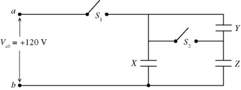
A) 94 V
B) 87 V
C) 79 V
D) 71 V
E) 63 V
Correct Answer:
Verified
Q24: The capacitors in the network shown in
Q25: In the circuit shown in the figure,
Q26: Three capacitors, with capacitances C1 = 4.0
Q28: A 1.0 m long piece of coaxial
Q29: Three capacitors,of capacitance 5.00 μF,10.0 μF,and 50.0
Q30: The capacitive network shown in the figure
Q31: A cylindrical capacitor is made of two
Q32: Three capacitors are arranged as shown in
Q33: An isolated air-filled parallel-plate capacitor that is
Q35: A 6.00-μF parallel-plate capacitor has charges of
Unlock this Answer For Free Now!
View this answer and more for free by performing one of the following actions

Scan the QR code to install the App and get 2 free unlocks

Unlock quizzes for free by uploading documents