Refer to the figure below to answer the following questions.
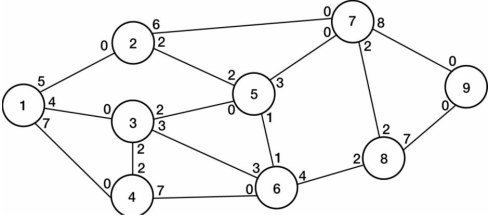 Figure 3
-Consider the network diagram given in Figure 3 with the indicated flow capacities along each branch. Determine the maximal flow on the following path: node 1 to node 2 to node 7 to destination node 9.
Correct Answer:
Verified
Q61: If we wanted to represent an urban
Q62: Consider the network shown in the figure.
Q63: The origin node for this network is
Q64: Refer to the figure below to answer
Q65: In the linear programming formulation of the
Q67: In a network flow model, a directed
Q68: If we wanted to represent water resources
Q69: In a network modeling problem, the linear
Q70: Refer to the figure below to answer
Q71: Refer to the figure below to answer
Unlock this Answer For Free Now!
View this answer and more for free by performing one of the following actions

Scan the QR code to install the App and get 2 free unlocks

Unlock quizzes for free by uploading documents