Multiple Choice
Block No.2 of the PLC block diagram represents the: 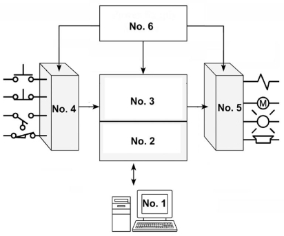
A) memory.
B) programming device.
C) input module.
D) power supply module.
Correct Answer:
Verified
Related Questions
Q2: The power required to operate the logic
Q8: The central processing unit
A)looks at the inputs,
Q20: The scan time is the time required
A)to
Q23: When a field device contact connected to
Q26: The programming device must be connected to
Q27: PLC proprietary architecture:
A)is the opposite to open
Unlock this Answer For Free Now!
View this answer and more for free by performing one of the following actions

Scan the QR code to install the App and get 2 free unlocks

Unlock quizzes for free by uploading documents