Block No.6 of the PLC block diagram represents the: 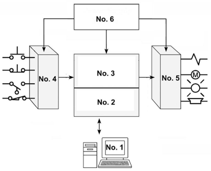
A) processor module.
B) power supply module.
C) input module.
D) output module.
Correct Answer:
Verified
Q44: Which of the following is not a
Q45: The devices connected to the terminals would
Q46: A control management PLC application normally requires
Q47: The diagram shown is a: 
Q48: Which module of the PLC is responsible
Q50: The diagram shown is that of a
Q51: PLC software that runs on a personal
Q52: The voltage that would be present between
Q53: The diagram shown is that of a:
Q54: In order to energize the starter coil:
Unlock this Answer For Free Now!
View this answer and more for free by performing one of the following actions

Scan the QR code to install the App and get 2 free unlocks

Unlock quizzes for free by uploading documents