Multiple Choice
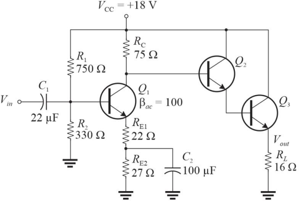 Figure 2 This is modification of Figure 1 (added Q2, Q3, and RL, deletion of C3 and a changed value of RE1) .
-Refer to Figure 2, which is a modified circuit from Figure 1. The voltage gain, AV, of this circuit is approximately
A) 3.3
B) 5.6
C) 2.0
D) 4.3
Correct Answer:
Verified
Related Questions
Q25: The ratio of Pout to PDC is
Q26: The Q point of a class- C
Q27: The maximum power from a class- A
Q28: In a class- AB amplifier, the transistors
Q29: Q30: In a class- B amplifier, the Q- Q31: The maximum ideal efficiency for a class- Unlock this Answer For Free Now! View this answer and more for free by performing one of the following actions Scan the QR code to install the App and get 2 free unlocks Unlock quizzes for free by uploading documents![]()

