 Figure 5 (This is similar to Figure 4 but uses a pnp transistor with the same fi.)
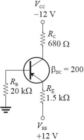
-Refer to Figure 5. The expected emitter voltage is
A) the same as the collector voltage in the npn circuit
B) the same as the npn circuit
C) the same as the collector voltage in the npn circuit except for the sign
D) the same as the npn circuit except for the sign
Correct Answer:
Verified
Q5: Q6: Q7: Refer to Figure 6. Assume VC = Q8: Assume a pnp transistor is used in Q9: Q11: Q12: A stiff voltage divider is one in Q13: Assume a load line is drawn for Q14: Q15: Unlock this Answer For Free Now! View this answer and more for free by performing one of the following actions Scan the QR code to install the App and get 2 free unlocks Unlock quizzes for free by uploading documents![]()
![]()
![]()
![]()
![]()
![]()

