For the circuit shown in the figure, the ideal battery has an emf . The four resistors have resistances of , and . Calculate the rate at which heat is being generated in the resistor .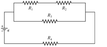
Correct Answer:
Verified
Q301: A portion of a circuit is
Q302: For the circuit shown in the
Q303: A multiloop circuit is shown in
Q304: Three resistors with resistances of
Q305: Determine the current in the
Q307: For the circuit shown in the
Q308: For the circuit shown in the
Q309: For the circuit shown in the
Q310: In the circuit shown in the
Q311: For the circuit shown in the
Unlock this Answer For Free Now!
View this answer and more for free by performing one of the following actions

Scan the QR code to install the App and get 2 free unlocks

Unlock quizzes for free by uploading documents