Short Answer
For the circuit shown in the figure, , , and the batteries are ideal.
(a) Determine and .
(b) What is the potential difference across ?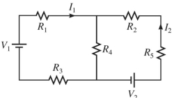
Correct Answer:
Verified
Related Questions
Q302: For the circuit shown in the
Q303: A multiloop circuit is shown in
Q304: Three resistors with resistances of
Q305: Determine the current in the
Q306: For the circuit shown in the
Q308: For the circuit shown in the
Q309: For the circuit shown in the
Q310: In the circuit shown in the
Q311: For the circuit shown in the
Q312: An ideal
Unlock this Answer For Free Now!
View this answer and more for free by performing one of the following actions

Scan the QR code to install the App and get 2 free unlocks

Unlock quizzes for free by uploading documents