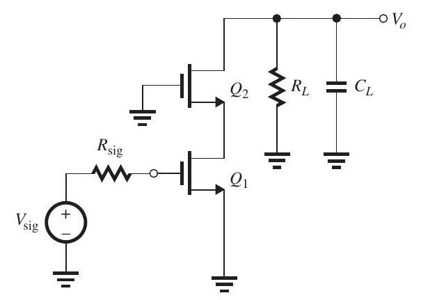
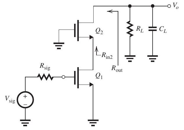
Solved

Figure 105 gm=2 mA/Vg_{m}=2 \mathrm{~mA} / \mathrm{V} And ro=20kΩr_{o}=20 \mathrm{k} \Omega And Has Rsig =RL=20kΩR_{\text {sig }}=R_{L}=20 \mathrm{k} \Omega

Question 5

Essay

     Figure 10.5.1      Figure 10.5.2 (a) The MOSFET in the common-source amplifier in Fig. 10.5.1, where the dc bias arrangement is not shown, is operating at  g_{m}=2 \mathrm{~mA} / \mathrm{V}  and  r_{o}=20 \mathrm{k} \Omega  and has  R_{\text {sig }}=R_{L}=20 \mathrm{k} \Omega . The transistor capacitances are specified as  C_{g s}=40 \mathrm{fF}  and  C_{g d}=C_{d b}=10 \mathrm{fF} . Also, there is an additional capacitance between the output node and ground,  C_{L}=10 \mathrm{fF} . Find the overall de gain  G_{v} \equiv V_{o} / V_{\text {sig }} , the upper 3-dB frequency  f_{H} , and the gain-bandwidth product  f_{t} . To determine  f_{H} , use the method of open-circuit time constants and recall that the resistance seen by  C_{g d}  is given by  R_{g d}=\left(1+g_{m} R_{L}^{\prime}\right) R_{\text {sig }}+R_{L}^{\prime} , where  R_{L}^{\prime}=R_{L} \| r_{o} . (b) To increase  f_{t} , the common-source transistor  Q_{1}  is cascoded as shown in Fig. 10.5.2 (refer to Figure above), where the dc bias arrangement is not shown. For the same values of  R_{\mathrm{sig}}, R_{L} , and  C_{L}  as in (a), assuming  Q_{1}  and  Q_{2}  are biased so that  g_{m 1}=g_{m 2}=2 \mathrm{~mA} / \mathrm{V}  and  r_{o 1}=r_{o 2}=20 \mathrm{k} \Omega , and for the capacitances of  Q_{1}  and  Q_{2}  to have the same values as specified in (a) above, find  G_{v}, f_{H} , and  f_{t}  for the cascode amplifier. Recall that  R_{\text {out }} \simeq\left(g_{m} r_{o}\right) r_{o}  and  R_{\text {in } 2}=\frac{1}{g_{m 2}}+\frac{R_{L}}{g_{m 2} r_{o 2}} . In using the open-circuit time-constants method, adapt the formula given in (a) for  R_{g d}  to obtain  R_{g d 1} . By what factor is  f_{t}  increased?

Figure 10.5.1
     Figure 10.5.1      Figure 10.5.2 (a) The MOSFET in the common-source amplifier in Fig. 10.5.1, where the dc bias arrangement is not shown, is operating at  g_{m}=2 \mathrm{~mA} / \mathrm{V}  and  r_{o}=20 \mathrm{k} \Omega  and has  R_{\text {sig }}=R_{L}=20 \mathrm{k} \Omega . The transistor capacitances are specified as  C_{g s}=40 \mathrm{fF}  and  C_{g d}=C_{d b}=10 \mathrm{fF} . Also, there is an additional capacitance between the output node and ground,  C_{L}=10 \mathrm{fF} . Find the overall de gain  G_{v} \equiv V_{o} / V_{\text {sig }} , the upper 3-dB frequency  f_{H} , and the gain-bandwidth product  f_{t} . To determine  f_{H} , use the method of open-circuit time constants and recall that the resistance seen by  C_{g d}  is given by  R_{g d}=\left(1+g_{m} R_{L}^{\prime}\right) R_{\text {sig }}+R_{L}^{\prime} , where  R_{L}^{\prime}=R_{L} \| r_{o} . (b) To increase  f_{t} , the common-source transistor  Q_{1}  is cascoded as shown in Fig. 10.5.2 (refer to Figure above), where the dc bias arrangement is not shown. For the same values of  R_{\mathrm{sig}}, R_{L} , and  C_{L}  as in (a), assuming  Q_{1}  and  Q_{2}  are biased so that  g_{m 1}=g_{m 2}=2 \mathrm{~mA} / \mathrm{V}  and  r_{o 1}=r_{o 2}=20 \mathrm{k} \Omega , and for the capacitances of  Q_{1}  and  Q_{2}  to have the same values as specified in (a) above, find  G_{v}, f_{H} , and  f_{t}  for the cascode amplifier. Recall that  R_{\text {out }} \simeq\left(g_{m} r_{o}\right) r_{o}  and  R_{\text {in } 2}=\frac{1}{g_{m 2}}+\frac{R_{L}}{g_{m 2} r_{o 2}} . In using the open-circuit time-constants method, adapt the formula given in (a) for  R_{g d}  to obtain  R_{g d 1} . By what factor is  f_{t}  increased?

Figure 10.5.2
(a) The MOSFET in the common-source amplifier in Fig. 10.5.1, where the dc bias arrangement is not shown, is operating at gm=2 mA/Vg_{m}=2 \mathrm{~mA} / \mathrm{V} and ro=20kΩr_{o}=20 \mathrm{k} \Omega and has Rsig =RL=20kΩR_{\text {sig }}=R_{L}=20 \mathrm{k} \Omega . The transistor capacitances are specified as Cgs=40fFC_{g s}=40 \mathrm{fF} and Cgd=Cdb=10fFC_{g d}=C_{d b}=10 \mathrm{fF} . Also, there is an additional capacitance between the output node and ground, CL=10fFC_{L}=10 \mathrm{fF} . Find the overall de gain GvVo/Vsig G_{v} \equiv V_{o} / V_{\text {sig }} , the upper 3-dB frequency fHf_{H} , and the gain-bandwidth product ftf_{t} . To determine fHf_{H} , use the method of open-circuit time constants and recall that the resistance seen by CgdC_{g d} is given by Rgd=(1+gmRL)Rsig +RLR_{g d}=\left(1+g_{m} R_{L}^{\prime}\right) R_{\text {sig }}+R_{L}^{\prime} , where RL=RLroR_{L}^{\prime}=R_{L} \| r_{o} .
(b) To increase ftf_{t} , the common-source transistor Q1Q_{1} is cascoded as shown in Fig. 10.5.2 (refer to Figure above), where the dc bias arrangement is not shown. For the same values of Rsig,RLR_{\mathrm{sig}}, R_{L} , and CLC_{L} as in (a), assuming Q1Q_{1} and Q2Q_{2} are biased so that gm1=gm2=2 mA/Vg_{m 1}=g_{m 2}=2 \mathrm{~mA} / \mathrm{V} and ro1=ro2=20kΩr_{o 1}=r_{o 2}=20 \mathrm{k} \Omega , and for the capacitances of Q1Q_{1} and Q2Q_{2} to have the same values as specified in (a) above, find Gv,fHG_{v}, f_{H} , and ftf_{t} for the cascode amplifier. Recall that Rout (gmro)roR_{\text {out }} \simeq\left(g_{m} r_{o}\right) r_{o} and Rin 2=1gm2+RLgm2ro2R_{\text {in } 2}=\frac{1}{g_{m 2}}+\frac{R_{L}}{g_{m 2} r_{o 2}} .
In using the open-circuit time-constants method, adapt the formula given in (a) for RgdR_{g d} to obtain Rgd1R_{g d 1} . By what factor is ftf_{t} increased?

Correct Answer:

verifed

Verified

(a)
blured image

Figure 10.5.1
blured image

Figure 10.5.2
...

View Answer

Unlock this answer now
Get Access to more Verified Answers free of charge

Related Questions

Unlock this Answer For Free Now!

View this answer and more for free by performing one of the following actions

qr-code

Scan the QR code to install the App and get 2 free unlocks

upload documents

Unlock quizzes for free by uploading documents