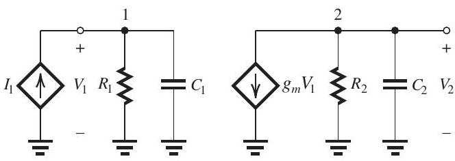
Solved

Figure 119 100 dB100 \mathrm{~dB} And Three Real-Axis Poles with Frequencies fP1=104 Hzf_{P 1}=10^{4} \mathrm{~Hz}

Question 9

Essay

     Figure 11.9.1 An op amp has a dc gain of  100 \mathrm{~dB}  and three real-axis poles with frequencies  f_{P 1}=10^{4} \mathrm{~Hz} ,  f_{P 2}=10^{5} \mathrm{~Hz} , and  f_{P 3}=10^{6} \mathrm{~Hz} . The op-amp internal circuit includes an amplifier stage having the equivalent circuit shown in Fig. 11.9.1, where  C_{1}=100 \mathrm{pF}, g_{m}=20 \mathrm{~mA} / \mathrm{V} , and  C_{2}=10 \mathrm{pF} . Furthermore, it is found that the input circuit of this stage is responsible for the pole at  f_{P 1}  and that the output circuit is responsible for the pole at  f_{P 2} . It is required to frequency-compensate this op amp so that it becomes stable in closed-loop configurations with a closed-loop gain as low as unity. (a) Sketch and clearly label a Bode plot for the op amp gain. Use a frequency axis that extends from  0.1 \mathrm{~Hz}  to  10^{7} \mathrm{~Hz} . (b) If the frequency compensation is achieved by connecting a capacitor  C_{C}  in parallel with  C_{1} , find the required value of  C_{C}  and sketch the modified gain response on your Bode plot. (c) If the frequency compensation is achieved by placing a capacitor  C_{f}  in the feedback path of the amplifier stage in Fig. 11.9.1 -that is, between nodes 1 and 2 (Miller compensation)-find the required value of  C_{f} . Also, find the new frequencies of the poles and sketch the modified gain on your Bode plot.

Figure 11.9.1
An op amp has a dc gain of 100 dB100 \mathrm{~dB} and three real-axis poles with frequencies fP1=104 Hzf_{P 1}=10^{4} \mathrm{~Hz} , fP2=105 Hzf_{P 2}=10^{5} \mathrm{~Hz} , and fP3=106 Hzf_{P 3}=10^{6} \mathrm{~Hz} . The op-amp internal circuit includes an amplifier stage having the equivalent circuit shown in Fig. 11.9.1, where C1=100pF,gm=20 mA/VC_{1}=100 \mathrm{pF}, g_{m}=20 \mathrm{~mA} / \mathrm{V} , and C2=10pFC_{2}=10 \mathrm{pF} . Furthermore, it is found that the input circuit of this stage is responsible for the pole at fP1f_{P 1} and that the output circuit is responsible for the pole at fP2f_{P 2} . It is required to frequency-compensate this op amp so that it becomes stable in closed-loop configurations with a closed-loop gain as low as unity.
(a) Sketch and clearly label a Bode plot for the op amp gain. Use a frequency axis that extends from 0.1 Hz0.1 \mathrm{~Hz} to 107 Hz10^{7} \mathrm{~Hz} .
(b) If the frequency compensation is achieved by connecting a capacitor CCC_{C} in parallel with C1C_{1} , find the required value of CCC_{C} and sketch the modified gain response on your Bode plot.
(c) If the frequency compensation is achieved by placing a capacitor CfC_{f} in the feedback path of the amplifier stage in Fig. 11.9.1 -that is, between nodes 1 and 2 (Miller compensation)-find the required value of CfC_{f} . Also, find the new frequencies of the poles and sketch the modified gain on your Bode plot.

Correct Answer:

verifed

Verified

blured image

(a) See Fig. 11.9.2.
(b)
\[\begin{al ...

View Answer

Unlock this answer now
Get Access to more Verified Answers free of charge

Related Questions

Unlock this Answer For Free Now!

View this answer and more for free by performing one of the following actions

qr-code

Scan the QR code to install the App and get 2 free unlocks

upload documents

Unlock quizzes for free by uploading documents