In the circuit shown in Figure 7-26,if the base voltage measured 0 V and the emitter voltage measured 0 V,what should the troubleshooter do? 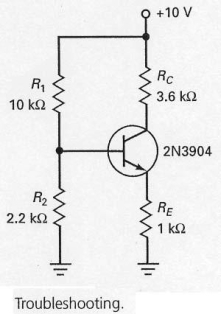
A) replace the transistor
B) replace RE
C) check R1
D) check voltage source and leads
Correct Answer:
Verified
Q5: If RE is adjusted to its maximum
Q6: Emitter-feedback bias uses a resistor that provides
Q7: Emitter-feedback bias is also called self-bias.
Q8: Emitter-feedback and collector-feedback are typically not adequate
Q9: The emitter-base junction voltage of the silicon
Q11: In the circuit shown in Figure 7-26,if
Q12: In the circuit shown in Figure 7-12,the
Q13: Voltage-divider bias is really emitter bias in
Q14: Collector-feedback bias is also called
A) self-bias.
B) collector
Q15: A well-designed voltage-divider bias circuit is one
Unlock this Answer For Free Now!
View this answer and more for free by performing one of the following actions

Scan the QR code to install the App and get 2 free unlocks

Unlock quizzes for free by uploading documents