In the circuit shown in Figure 7-26,if R1 opens 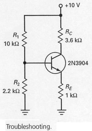
A) the collector voltage will be 10 V.
B) the collector voltage will be 0 V.
C) the base voltage will be 10 V.
D) the emitter voltage will be 10 V.
Correct Answer:
Verified
Q6: Emitter-feedback bias uses a resistor that provides
Q7: Emitter-feedback bias is also called self-bias.
Q8: Emitter-feedback and collector-feedback are typically not adequate
Q9: The emitter-base junction voltage of the silicon
Q10: In the circuit shown in Figure 7-26,if
Q12: In the circuit shown in Figure 7-12,the
Q13: Voltage-divider bias is really emitter bias in
Q14: Collector-feedback bias is also called
A) self-bias.
B) collector
Q15: A well-designed voltage-divider bias circuit is one
Q16: Since voltage-divider bias is derived from emitter
Unlock this Answer For Free Now!
View this answer and more for free by performing one of the following actions

Scan the QR code to install the App and get 2 free unlocks

Unlock quizzes for free by uploading documents