A galvanometer G has an internal resistance rg. An AMMETER is constructed by incorporating the galvanometer and an additional resistance Rs. Which one of the figures below is the most appropriate circuit diagram for the ammeter? 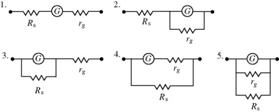
A) 1
B) 2
C) 3
D) 4
E) 5
Correct Answer:
Verified
Q1: Two unknown resistors are connected together.When they
Q6: In the circuit shown in the figure,
Q9: Thirteen resistors are connected across points A
Q10: A light bulb is connected in the
Q12: An RC circuit is connected across an
Q13: In the circuit shown in the figure,
Q14: A galvanometer G has an internal resistance
Q15: A resistor is made out of a
Q16: As more resistors are added in parallel
Q20: A 5.0-Ω resistor and a 9.0-Ω resistor
Unlock this Answer For Free Now!
View this answer and more for free by performing one of the following actions

Scan the QR code to install the App and get 2 free unlocks

Unlock quizzes for free by uploading documents