In the circuit shown in the figure, an ideal ohmmeter is connected across ab with the switch S open. All the connecting leads have negligible resistance. The reading of the ohmmeter will be closest to 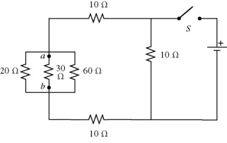
A) 7.5 Ω.
B) 10 Ω.
C) 30 Ω.
D) 40 Ω.
E) 60 Ω.
Correct Answer:
Verified
Q1: Two unknown resistors are connected together.When they
Q9: Thirteen resistors are connected across points A
Q10: A light bulb is connected in the
Q11: A galvanometer G has an internal resistance
Q14: A galvanometer G has an internal resistance
Q15: A resistor is made out of a
Q16: As more resistors are added in parallel
Q17: Four resistors are connected across an 8-V
Q18: In the circuit shown in the figure,
Q20: A 5.0-Ω resistor and a 9.0-Ω resistor
Unlock this Answer For Free Now!
View this answer and more for free by performing one of the following actions

Scan the QR code to install the App and get 2 free unlocks

Unlock quizzes for free by uploading documents